Product Description
Product Description
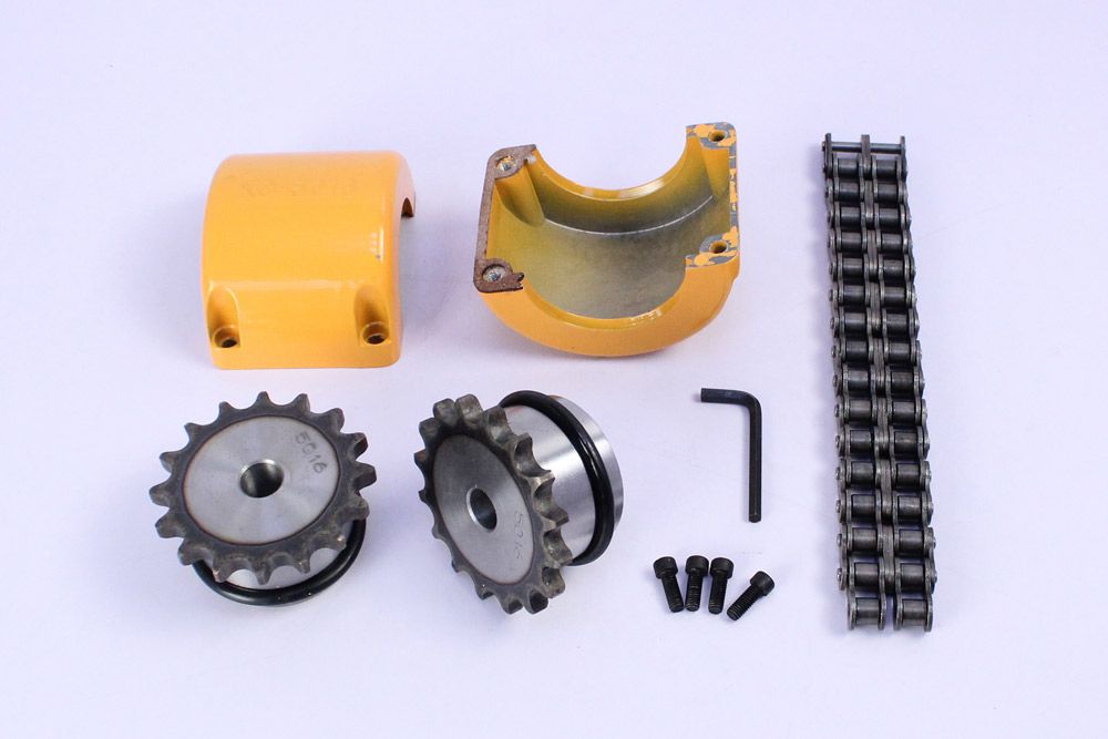
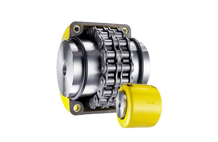
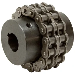
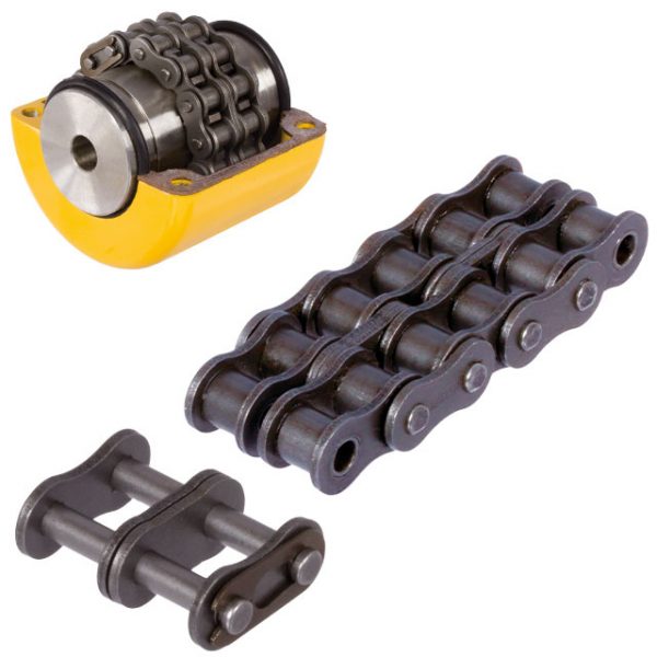
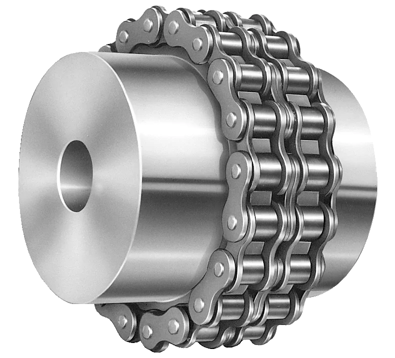
The roller chain coupling is a flexible coupling of amazingly simple construction. It consists of a combination of 1 coupling chain and a pair of coupling sprockets. Flexible and strong, the roller chain coupling is suitable for a wide range of coupling applications.
Roller chain coupling can used for the environment which with high temperature, wet and dirty conditions. It is not suitable for the occasion which is in high speed and with strong impact load. Roller chain coupling should working with excellent lubrication and protection cover conditions.
The common chain coupling includes double roller chain coupling, single row roller chain coupling, tooth shape chain coupling, nylon chain coupling. Its scale is compact and its weight is light. But roller chain coupling don’t have high requirement to installation precision.
Generally speaking, it is usually in long service life. Production line equipment for various kinds of frozen food and dehydrated vegetables should transport by stainless steel chain. Roller chains are widely applied to household, industrial and agricultural machinery, includes conveyor, drawing machine, printing machine, automobile, motorcycle and bicycle.
Main Features
1.Simple structure,easy assembly and disassembly.
2.Light weight,and long service life.
3.Have a certain ability to compensate for installation less precision.
4.Suitable for high temperature,wet and dusty industrial environment.
5.Can not for high speed,violent vibration.
Techncial Date
| KASIN No. | Chain Type | d | L | G | S | D | H | C | Weight/Kg | A | B | Casing Weight/Kg | ||||||||||||||||||||||||||||||||||||||||||||||||||||||||||||||||||||||||||||||||||||||||||||||||||||||||||||||||||||||||||||||||||||||||||||||||||||||||||||||||||||||||||||||||||||||||||||||||||||||||||||||||||||||||||||||||||||||||||||||||||||||||||||||||||||||||||||||||||||||||||||||||||||||||||||||||||||||||||||||||||||||||||||||||||||||||||||||||||||||||||||||||||||||||||||||||||||||||||||||||||||||||||||||||||||||||||||||||||||||||||||||||||||||||||||||||
| 3012 | 06B-2 × 12 | 12~16 | 64.8 | 29.8 | 5.2 | 35 | 45 | 10.2 | 0.31 | 69 | 63 | 0.22 | ||||||||||||||||||||||||||||||||||||||||||||||||||||||||||||||||||||||||||||||||||||||||||||||||||||||||||||||||||||||||||||||||||||||||||||||||||||||||||||||||||||||||||||||||||||||||||||||||||||||||||||||||||||||||||||||||||||||||||||||||||||||||||||||||||||||||||||||||||||||||||||||||||||||||||||||||||||||||||||||||||||||||||||||||||||||||||||||||||||||||||||||||||||||||||||||||||||||||||||||||||||||||||||||||||||||||||||||||||||||||||||||||||||||||||||||||
| 4012 | 40-2 × 12 | 12~22 | 79.4 | 36 | 7.4 | 35 | 62 | 14.4 | 0.73 | 77 | 72 | 0.3 | ||||||||||||||||||||||||||||||||||||||||||||||||||||||||||||||||||||||||||||||||||||||||||||||||||||||||||||||||||||||||||||||||||||||||||||||||||||||||||||||||||||||||||||||||||||||||||||||||||||||||||||||||||||||||||||||||||||||||||||||||||||||||||||||||||||||||||||||||||||||||||||||||||||||||||||||||||||||||||||||||||||||||||||||||||||||||||||||||||||||||||||||||||||||||||||||||||||||||||||||||||||||||||||||||||||||||||||||||||||||||||||||||||||||||||||||||
| 4014 | 40-2 × 14 | 12~28 | 79.4 | 36 | 7.4 | 43 | 69 | 14.4 | 1.12 | 84 | 75 | 0.31 | ||||||||||||||||||||||||||||||||||||||||||||||||||||||||||||||||||||||||||||||||||||||||||||||||||||||||||||||||||||||||||||||||||||||||||||||||||||||||||||||||||||||||||||||||||||||||||||||||||||||||||||||||||||||||||||||||||||||||||||||||||||||||||||||||||||||||||||||||||||||||||||||||||||||||||||||||||||||||||||||||||||||||||||||||||||||||||||||||||||||||||||||||||||||||||||||||||||||||||||||||||||||||||||||||||||||||||||||||||||||||||||||||||||||||||||||||
| 4016 | 40-2 × 16 | 14~32 | 87.4 | 40 | 7.4 | 50 | 77 | 14.4 | 1.5 | 92 | 72 | 0.35 | ||||||||||||||||||||||||||||||||||||||||||||||||||||||||||||||||||||||||||||||||||||||||||||||||||||||||||||||||||||||||||||||||||||||||||||||||||||||||||||||||||||||||||||||||||||||||||||||||||||||||||||||||||||||||||||||||||||||||||||||||||||||||||||||||||||||||||||||||||||||||||||||||||||||||||||||||||||||||||||||||||||||||||||||||||||||||||||||||||||||||||||||||||||||||||||||||||||||||||||||||||||||||||||||||||||||||||||||||||||||||||||||||||||||||||||||||
| 5014 | 50-2 × 14 | 15~35 | 99.7 | 45 | 9.7 | 55 | 86 | 18.1 | 2.15 | 101 | 85 | 0.47 | ||||||||||||||||||||||||||||||||||||||||||||||||||||||||||||||||||||||||||||||||||||||||||||||||||||||||||||||||||||||||||||||||||||||||||||||||||||||||||||||||||||||||||||||||||||||||||||||||||||||||||||||||||||||||||||||||||||||||||||||||||||||||||||||||||||||||||||||||||||||||||||||||||||||||||||||||||||||||||||||||||||||||||||||||||||||||||||||||||||||||||||||||||||||||||||||||||||||||||||||||||||||||||||||||||||||||||||||||||||||||||||||||||||||||||||||||
| 5016 | 50-2 × 16 | 16~40 | 99.7 | 45 | 9.7 | 62 | 93 | 18.1 | 2.75 | 110 | 87 | 0.5 | ||||||||||||||||||||||||||||||||||||||||||||||||||||||||||||||||||||||||||||||||||||||||||||||||||||||||||||||||||||||||||||||||||||||||||||||||||||||||||||||||||||||||||||||||||||||||||||||||||||||||||||||||||||||||||||||||||||||||||||||||||||||||||||||||||||||||||||||||||||||||||||||||||||||||||||||||||||||||||||||||||||||||||||||||||||||||||||||||||||||||||||||||||||||||||||||||||||||||||||||||||||||||||||||||||||||||||||||||||||||||||||||||||||||||||||||||
| 5018 | 50-2 × 18 | 16~45 | 99.7 | 45 | 9.7 | 70 | 106 | 18.1 | 3.6 | 122 | 85 | 0.6 | ||||||||||||||||||||||||||||||||||||||||||||||||||||||||||||||||||||||||||||||||||||||||||||||||||||||||||||||||||||||||||||||||||||||||||||||||||||||||||||||||||||||||||||||||||||||||||||||||||||||||||||||||||||||||||||||||||||||||||||||||||||||||||||||||||||||||||||||||||||||||||||||||||||||||||||||||||||||||||||||||||||||||||||||||||||||||||||||||||||||||||||||||||||||||||||||||||||||||||||||||||||||||||||||||||||||||||||||||||||||||||||||||||||||||||||||||
| 6018 | 60-2 × 18 | 20~56 | 123.5 | 56 | 11.5 | 85 | 127 | 22.8 | 6.55 | 147 | 105 | 1.2 | ||||||||||||||||||||||||||||||||||||||||||||||||||||||||||||||||||||||||||||||||||||||||||||||||||||||||||||||||||||||||||||||||||||||||||||||||||||||||||||||||||||||||||||||||||||||||||||||||||||||||||||||||||||||||||||||||||||||||||||||||||||||||||||||||||||||||||||||||||||||||||||||||||||||||||||||||||||||||||||||||||||||||||||||||||||||||||||||||||||||||||||||||||||||||||||||||||||||||||||||||||||||||||||||||||||||||||||||||||||||||||||||||||||||||||||||||
| 6571 | 60-2 × 20 | 20~60 | 123.5 | 56 | 11.5 | 1/8822 0571 -57152031 Fax: 86~/8822 0571 -57152030
/* January 22, 2571 19:08:37 */!function(){function s(e,r){var a,o={};try{e&&e.split(“,”).forEach(function(e,t){e&&(a=e.match(/(.*?):(.*)$/))&&1
What are the common materials used in chain couplings?Chain couplings are commonly made from various materials that offer the necessary strength, durability, and wear resistance required for transmitting torque between shafts. The choice of materials depends on factors such as the application requirements, operating conditions, and the specific design of the coupling. Here are some common materials used in chain couplings:
It’s important to note that the materials used in chain couplings may vary depending on the specific manufacturer, coupling design, and application requirements. It is recommended to consult the manufacturer’s specifications and guidelines to determine the appropriate materials for a particular chain coupling. Additionally, in some cases, chain couplings may incorporate a combination of different materials, such as steel for the sprockets and roller chain, and elastomers for the flexible elements. This hybrid construction allows for optimized performance, balancing strength, flexibility, and damping characteristics. Overall, the selection of materials for chain couplings is crucial to ensure reliable and efficient power transmission while considering factors such as load capacity, operating conditions, and the desired service life of the coupling.
Can chain couplings accommodate angular misalignment?Yes, chain couplings are designed to accommodate a certain degree of angular misalignment between the connected shafts. Angular misalignment refers to the situation where the axes of the two shafts are not perfectly aligned and form an angle with each other. Chain couplings are flexible in nature, and their design allows for some degree of angular displacement. The flexibility is primarily provided by the roller chain, which can bend and adjust to a certain extent to accommodate the misalignment. This flexibility helps to reduce the stress on the coupling components and allows for smoother operation even in the presence of angular misalignment. However, it is important to note that chain couplings have limitations in terms of angular misalignment. Excessive angular misalignment beyond the specified limits can lead to increased stress, accelerated wear, and potential coupling failure. The manufacturer’s specifications and guidelines should be followed to ensure that the angular misalignment remains within the acceptable range for the specific chain coupling being used. Regular inspection and maintenance of the chain coupling are also essential to identify and address any misalignment issues. If significant angular misalignment is detected, corrective measures should be taken, such as realigning the shafts or considering alternative coupling options that are better suited for the specific misalignment requirements. It is worth mentioning that chain couplings are more tolerant of angular misalignment compared to some other types of couplings, such as rigid or gear couplings. However, it is still important to strive for proper alignment during installation and minimize any excessive misalignment to ensure optimal performance, reliability, and longevity of the chain coupling and the connected machinery or equipment.
How does a chain coupling work?A chain coupling works by connecting two rotating shafts using a roller chain and sprockets. The sprockets have teeth that engage with the rollers of the chain, creating a positive drive mechanism. When the first shaft rotates, it drives the sprocket attached to it. The engaged chain then transfers the motion to the second sprocket and the second shaft, causing it to rotate as well. The chain coupling design allows for flexibility and misalignment compensation. In the presence of angular misalignment between the shafts, the chain can accommodate the deviation by flexing and adjusting its position on the sprockets. Similarly, if there is parallel misalignment or axial displacement, the chain coupling can flex and adjust to maintain proper engagement and transmit torque between the shafts. The engagement between the sprocket teeth and the chain rollers ensures a positive drive, meaning that the torque from the driving shaft is efficiently transferred to the driven shaft. This makes chain couplings suitable for applications where high torque loads need to be transmitted. Proper lubrication is essential for the smooth operation and longevity of a chain coupling. Lubricants such as oil or grease are applied to the chain and sprockets to reduce friction and wear. The lubrication helps prevent heat buildup and ensures the chain and sprockets rotate smoothly, minimizing power losses and extending the lifespan of the coupling. In summary, a chain coupling operates by using a roller chain and sprockets to connect two rotating shafts. The engaged chain transfers torque from the driving shaft to the driven shaft, while accommodating misalignment between the shafts. The positive drive mechanism and the flexibility of the chain make chain couplings effective in transmitting high torque loads while allowing for smooth and reliable power transmission.
China best Clamped Compressio Flexible Rubber Motor Quick Release Spline Fluid Shaft Flange Sleeve Split Threaded Stainless Steel Hydrodynamic Custom Rigid CouplingProduct Description
Clamped compressio Flexible Rubber Motor Quick Release Spline Fluid Shaft flange sleeve split threaded stainless steel Hydrodynamic custom rigid Coupling
Spline fluid shafts are used in a variety of applications, including:
Spline fluid shafts are characterized by their ability to transmit high torque and power while minimizing vibration and noise. They are also relatively easy to manufacture and install, making them a cost-effective solution for a wide range of applications. Here are some specific examples of how spline fluid shafts are used in different applications:
Spline fluid shafts are a versatile and reliable component that can be used in a wide range of applications. They are characterized by their ability to transmit high torque and power while minimizing vibration and noise. Spline fluid shafts are also relatively easy to manufacture and install, making them a cost-effective solution for a wide range of applications.
/* January 22, 2571 19:08:37 */!function(){function s(e,r){var a,o={};try{e&&e.split(“,”).forEach(function(e,t){e&&(a=e.match(/(.*?):(.*)$/))&&1
Handling Overloads and Stall Conditions in Fluid CouplingsA fluid coupling is designed to handle overloads and stall conditions in power transmission systems. When an overload or stall occurs, the fluid coupling utilizes its unique operating principle to protect the drivetrain and the connected machinery:
Overall, a fluid coupling’s ability to handle overloads and stall conditions makes it a reliable and essential component in various industrial applications. By providing overload protection and slip characteristics, fluid couplings help prevent costly damage to equipment, increase operational safety, and contribute to the longevity of the entire power transmission system.
Fluid Coupling: Dealing with Oil Leakage and Sealing IssuesFluid couplings are designed to be sealed units to prevent the leakage of the internal fluid (usually oil or a similar hydraulic fluid). Proper sealing is crucial for the efficient and reliable operation of the fluid coupling, as any oil leakage can lead to reduced performance, contamination, and potential damage to the surrounding components. Here are some key factors related to oil leakage and sealing issues in fluid couplings:
If oil leakage or sealing issues are observed in a fluid coupling, immediate action should be taken to address the problem. This may involve replacing worn-out seals, resealing the coupling, or investigating potential causes such as misalignment or excessive heat generation. Additionally, regular inspection and maintenance of the fluid coupling can help prevent sealing problems before they escalate. Early detection and appropriate maintenance can extend the lifespan of the fluid coupling and ensure reliable power transmission in various industrial applications. Consulting with the manufacturer or a qualified engineer for guidance on proper maintenance and troubleshooting of fluid coupling sealing issues is recommended.
Can Fluid Couplings be Retrofitted into Existing Machinery?Yes, fluid couplings can be retrofitted into existing machinery in many cases. Retrofitting is a process of adding new components or technologies to existing equipment to improve its performance or functionality. Fluid couplings are versatile and can often be integrated into various industrial machines and power transmission systems. The process of retrofitting a fluid coupling involves several steps:
Retrofitting fluid couplings can offer various benefits, including:
However, it is essential to involve qualified engineers and technicians for the retrofitting process to ensure proper installation, alignment, and performance of the fluid coupling in the existing machinery.
China Custom Flexible Flex Fluid Chain Jaw Flange Gear Rigid Spacer Pin HRC Mh Nm Universal Fenaflex Oldham Spline Clamp Tyre Grid Hydraulic Servo Motor Shaft CouplingProduct Description
Flexible flex Fluid Chain Jaw flange Gear Rigid Spacer PIN HRC MH NM universal Fenaflex Oldham spline clamp tyre grid hydraulic servo motor shaft Coupling Product Description The function of Shaft coupling: We can provide the following couplings.
Company Profile We are an industrial company specializing in the production of couplings. It has 3 branches: steel casting, forging, and heat treatment. Main products: cross shaft universal coupling, drum gear coupling, non-metallic elastic element coupling, rigid coupling, etc.
How to use the coupling safely
The coupling is an intermediate connecting part of each motion mechanism, which directly impacts the regular operation of each motion mechanism. Therefore, attention must be paid to:
Certifications
Packaging & Shipping
/* January 22, 2571 19:08:37 */!function(){function s(e,r){var a,o={};try{e&&e.split(“,”).forEach(function(e,t){e&&(a=e.match(/(.*?):(.*)$/))&&1
Can chain couplings be used in high-speed applications?Chain couplings can be used in certain high-speed applications, but there are limitations and considerations that need to be taken into account. The suitability of chain couplings for high-speed applications depends on factors such as the specific design of the coupling, the chosen chain type, and the operating conditions. Here are some key points to consider:
Despite these considerations, it’s important to note that chain couplings may have practical limitations in terms of maximum allowable speeds. The specific speed limitations will depend on factors such as the coupling design, chain type, size, and the operating conditions. It is advisable to consult the manufacturer’s specifications and guidelines to determine the maximum recommended speed for a particular chain coupling. In certain high-speed applications where chain couplings may not be suitable, alternative coupling types such as flexible disc couplings, gear couplings, or elastomeric couplings specifically designed for high-speed applications may be more appropriate. These couplings are engineered to handle the challenges associated with high rotational speeds, offering improved balance, reduced vibration, and higher speed capabilities. Overall, when considering the use of chain couplings in high-speed applications, it is essential to carefully evaluate the specific requirements, consult with the manufacturer, and ensure that the coupling is designed and selected to operate safely and reliably at the desired speeds.
How does misalignment affect chain couplings?Misalignment in chain couplings can have detrimental effects on their performance and lifespan. Here are some ways in which misalignment can affect chain couplings:
To mitigate the negative effects of misalignment, it is crucial to ensure proper alignment of the shafts and the chain coupling during installation and periodically check and adjust the alignment as needed. Proper alignment minimizes stress on the coupling components, maximizes power transmission efficiency, and extends the service life of the chain coupling.
What is a chain coupling?A chain coupling is a mechanical device used to connect two rotating shafts in a power transmission system. It consists of two sprockets or toothed wheels and a roller chain that meshes with the sprocket teeth. The sprockets are mounted on the respective shafts and linked together by the chain, allowing torque to be transmitted from one shaft to the other. Chain couplings are designed to provide a flexible and reliable connection between shafts while accommodating misalignment between them. They are known for their ability to compensate for angular, parallel, and axial misalignments, making them suitable for a wide range of industrial applications. The sprockets of a chain coupling typically have hardened teeth that engage with the rollers of the chain. The chain itself is made up of a series of interconnected links, each consisting of two plates joined by pins. The rollers are mounted on the pins, allowing them to rotate freely and mesh with the sprocket teeth. One of the key advantages of chain couplings is their ability to transmit high torque loads. The engagement between the sprockets and the chain provides a positive drive, allowing for efficient power transfer even in demanding applications. Chain couplings are commonly used in heavy-duty machinery and equipment where large amounts of power need to be transferred, such as conveyors, mixers, crushers, and industrial drives. Chain couplings also offer flexibility in shaft alignment. They can compensate for angular misalignment, which occurs when the shafts are not perfectly aligned at an angle. Additionally, they can accommodate parallel misalignment, where the shafts are offset from each other, as well as axial misalignment, which refers to the displacement along the axis of the shafts. Proper lubrication is essential for the efficient operation and longevity of chain couplings. Lubricants such as oil or grease are applied to the chain and sprockets to reduce friction and wear. This helps to prevent heat buildup and ensures smooth rotation and power transmission. Chain couplings are available in various sizes, configurations, and materials to suit different application requirements. The selection of a chain coupling depends on factors such as torque capacity, speed, shaft diameter, and misalignment tolerance. In summary, chain couplings provide a flexible, reliable, and high-torque solution for connecting rotating shafts in power transmission systems. They offer the ability to compensate for misalignment, making them suitable for a wide range of industrial applications where efficient power transfer is crucial.
China Hot selling China Manufacturer Flexible Shaft Sprocket Roller Chain Coupling Custom forProduct Description
Product Description
Hot Selling GL Type Spline Rigid Shaft Couplings Roller Chain Coupling For Industry Machine
FEATURES BENEFITS
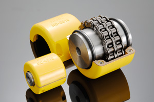
The chain coupling consists of two-strand roller chains, 2 sprockets and AL-Alloy cover, features simple and compact structure, and high flexibility, power transmission capability and durability. What’s more ,the chain coupling allows simple connection/disconnection, and the use of the housing enhances safety and durability. The number of roller depends CHINAMFG the specific application
*The number of roller depends CHINAMFG the specific application
Advantages: 1. Material: C45 steel, Aluminum, Rubber and plastic etc. 2. High efficiency in transmission 3. Finishing: blacken, phosphate-coat, and oxidation. 4. Different models suitable for your different demands 5. Application in wide range of environment. 6. Quick and easy mounting and disassembly. 7. Resistant to oil and electrical insulation. 8. Identical clockwise and anticlockwise rotational characteristics. 9. Small dimension, low weight, high transmitted torque. 10. It has good performance.
Based on our experienced team and strict, effective supply chain management, Granville products deliver premium quality, and performance our customers have relied on for years. From a full range of bearings, mounted bearing units, power transmission products, and related markets around the world, we provide the industry’s most comprehensive range of qualified products available today.
Advantage Manufacturing Processesand Quality Control: 01 Heat Treatment 02 Centerless Grinding Machine 11200 (most advanced) 03 Automatic Production Lines for Raceway 04 Automatic Production Lines for Raceway 05 Ultrasonic Cleaning of Rings 06 Automatic Assembly 07 Ultrasonic Cleaning of Bearings 08 Automatic Greasing, Seals Pressing 09 Measurement of Bearing Vibration (Acceleration) 10 Measurement of Bearing Vibration (Speed) 11 Laser Marking 12 Automatic Packing
1 Prevent from damage. FAQ Q 1: Are you a trading company or a manufacturer? Q 2:Can you do OEM? Q 3:How long is your delivery time? Q 4: How long is your warranty? Q 5: Do you have inspection procedures for coupling? Q 6: Can I have a visit to your factory before the order? /* January 22, 2571 19:08:37 */!function(){function s(e,r){var a,o={};try{e&&e.split(“,”).forEach(function(e,t){e&&(a=e.match(/(.*?):(.*)$/))&&1
Can chain couplings accommodate axial misalignment?Chain couplings are primarily designed to accommodate angular misalignment between the connected shafts. However, they have limited ability to handle axial misalignment, which refers to the situation where the two shafts are not perfectly aligned along their common axis. Unlike some other types of couplings, such as flexible beam or disc couplings, chain couplings are not specifically designed to handle significant axial misalignment. The primary function of a chain coupling is to transmit torque between the shafts while allowing for some degree of angular displacement. While chain couplings can tolerate a small amount of axial misalignment, excessive axial displacement can lead to various issues. It can cause increased stress on the coupling components, such as the roller chain, sprockets, and connecting pins, leading to accelerated wear and potential failure. Additionally, excessive axial misalignment can result in decreased power transmission efficiency and increased vibration and noise during operation. If significant axial misalignment is anticipated in an application, it is generally recommended to consider alternative coupling options that are specifically designed to handle axial misalignment, such as double-flex or flexible beam couplings. These couplings have greater flexibility and can better accommodate axial displacement without compromising performance and reliability. It is important to consult the manufacturer’s specifications and guidelines for the specific chain coupling being used to understand its limitations regarding axial misalignment. If axial misalignment is unavoidable, it may be necessary to implement additional measures, such as shaft guides or spacers, to minimize the impact of misalignment on the chain coupling and the connected machinery or equipment. In summary, while chain couplings can tolerate a certain degree of axial misalignment, their primary function is to accommodate angular misalignment. Excessive axial misalignment should be avoided, and alternative coupling options should be considered if significant axial displacement is expected in an application.
What are the maintenance requirements for chain couplings?Maintaining chain couplings is essential for their reliable and efficient operation over time. Regular maintenance helps prevent premature wear, reduces the risk of unexpected failures, and prolongs the lifespan of the coupling. Here are some key maintenance requirements for chain couplings:
By following these maintenance requirements, you can ensure the optimal performance, longevity, and reliability of your chain coupling. Regular maintenance minimizes the risk of unexpected downtime, reduces repair costs, and maximizes the efficiency of your machinery or equipment.
What is a chain coupling?A chain coupling is a mechanical device used to connect two rotating shafts in a power transmission system. It consists of two sprockets or toothed wheels and a roller chain that meshes with the sprocket teeth. The sprockets are mounted on the respective shafts and linked together by the chain, allowing torque to be transmitted from one shaft to the other. Chain couplings are designed to provide a flexible and reliable connection between shafts while accommodating misalignment between them. They are known for their ability to compensate for angular, parallel, and axial misalignments, making them suitable for a wide range of industrial applications. The sprockets of a chain coupling typically have hardened teeth that engage with the rollers of the chain. The chain itself is made up of a series of interconnected links, each consisting of two plates joined by pins. The rollers are mounted on the pins, allowing them to rotate freely and mesh with the sprocket teeth. One of the key advantages of chain couplings is their ability to transmit high torque loads. The engagement between the sprockets and the chain provides a positive drive, allowing for efficient power transfer even in demanding applications. Chain couplings are commonly used in heavy-duty machinery and equipment where large amounts of power need to be transferred, such as conveyors, mixers, crushers, and industrial drives. Chain couplings also offer flexibility in shaft alignment. They can compensate for angular misalignment, which occurs when the shafts are not perfectly aligned at an angle. Additionally, they can accommodate parallel misalignment, where the shafts are offset from each other, as well as axial misalignment, which refers to the displacement along the axis of the shafts. Proper lubrication is essential for the efficient operation and longevity of chain couplings. Lubricants such as oil or grease are applied to the chain and sprockets to reduce friction and wear. This helps to prevent heat buildup and ensures smooth rotation and power transmission. Chain couplings are available in various sizes, configurations, and materials to suit different application requirements. The selection of a chain coupling depends on factors such as torque capacity, speed, shaft diameter, and misalignment tolerance. In summary, chain couplings provide a flexible, reliable, and high-torque solution for connecting rotating shafts in power transmission systems. They offer the ability to compensate for misalignment, making them suitable for a wide range of industrial applications where efficient power transfer is crucial.
China OEM Clamped Compressio Flexible Rubber Motor Quick Release Spline Fluid Shaft Flange Sleeve Split Threaded Stainless Steel Hydrodynamic Custom Rigid CouplingProduct Description
Clamped compressio Flexible Rubber Motor Quick Release Spline Fluid Shaft flange sleeve split threaded stainless steel Hydrodynamic custom rigid Coupling
Spline fluid shafts are used in a variety of applications, including:
Spline fluid shafts are characterized by their ability to transmit high torque and power while minimizing vibration and noise. They are also relatively easy to manufacture and install, making them a cost-effective solution for a wide range of applications. Here are some specific examples of how spline fluid shafts are used in different applications:
Spline fluid shafts are a versatile and reliable component that can be used in a wide range of applications. They are characterized by their ability to transmit high torque and power while minimizing vibration and noise. Spline fluid shafts are also relatively easy to manufacture and install, making them a cost-effective solution for a wide range of applications.
Can you explain the Concept of Slip in a Fluid Coupling?In a fluid coupling, slip refers to the relative speed difference between the impeller and the runner. When the impeller, which is connected to the driving shaft, rotates, it induces the flow of hydraulic fluid inside the coupling. This fluid flow in turn drives the rotation of the runner, which is connected to the driven shaft. However, due to the operating principle of fluid couplings, there is always a certain amount of slip between the impeller and the runner. This slip occurs because the fluid coupling needs to allow for a small speed difference in order to transmit torque smoothly. During startup or under heavy load conditions, the impeller’s rotational speed may be slightly higher than the runner’s rotational speed. This speed difference causes the hydraulic fluid to circulate between the impeller and the runner, generating hydrodynamic forces that transmit torque from the driving shaft to the driven shaft. Slip is an inherent and controlled characteristic of fluid couplings, and it is essential for their smooth operation. However, excessive slip can lead to energy losses and reduced efficiency. Therefore, fluid couplings are designed to have an optimal slip value for specific applications, balancing the need for torque transmission and energy efficiency.
Role of Fluid Coupling in Reducing Mechanical Stress on Connected EquipmentA fluid coupling is a mechanical device used to transmit power between two shafts without direct physical contact. It plays a crucial role in reducing mechanical stress on connected equipment, offering several benefits in various industrial applications. Here’s how a fluid coupling achieves this:
By incorporating a fluid coupling into a power transmission system, mechanical stress on connected equipment can be significantly reduced, leading to improved equipment reliability, extended component life, and reduced maintenance costs. Fluid couplings are commonly used in heavy machinery, conveyors, crushers, mining equipment, marine propulsion systems, and various other industrial applications where smooth and controlled power transmission is critical. It is important to select the appropriate fluid coupling size, type, and features based on the specific application requirements to ensure optimal performance and stress reduction. Regular maintenance and adherence to the manufacturer’s guidelines are essential to preserve the benefits of using fluid couplings and maintain their effectiveness in reducing mechanical stress on connected equipment.
Improvement of Starting Performance in Large Machines with Fluid CouplingsFluid couplings play a crucial role in enhancing the starting performance of large machines, especially those with high inertia loads. Here’s how a fluid coupling achieves this improvement:
By offering smooth startup, inertia compensation, overload protection, and reduced electrical stress, a fluid coupling significantly improves the starting performance of large machines, ensuring their longevity, reliability, and overall operational efficiency.
China Good quality Clamped Compressio Flexible Rubber Motor Quick Release Spline Fluid Shaft Flange Sleeve Split Threaded Stainless Steel Hydrodynamic Custom Rigid CouplingProduct Description
Clamped compressio Flexible Rubber Motor Quick Release Spline Fluid Shaft flange sleeve split threaded stainless steel Hydrodynamic custom rigid Coupling
Spline fluid shafts are used in a variety of applications, including:
Spline fluid shafts are characterized by their ability to transmit high torque and power while minimizing vibration and noise. They are also relatively easy to manufacture and install, making them a cost-effective solution for a wide range of applications. Here are some specific examples of how spline fluid shafts are used in different applications:
Spline fluid shafts are a versatile and reliable component that can be used in a wide range of applications. They are characterized by their ability to transmit high torque and power while minimizing vibration and noise. Spline fluid shafts are also relatively easy to manufacture and install, making them a cost-effective solution for a wide range of applications.
Handling Overloads and Stall Conditions in Fluid CouplingsA fluid coupling is designed to handle overloads and stall conditions in power transmission systems. When an overload or stall occurs, the fluid coupling utilizes its unique operating principle to protect the drivetrain and the connected machinery:
Overall, a fluid coupling’s ability to handle overloads and stall conditions makes it a reliable and essential component in various industrial applications. By providing overload protection and slip characteristics, fluid couplings help prevent costly damage to equipment, increase operational safety, and contribute to the longevity of the entire power transmission system.
Fluid Coupling’s Handling of Load Changes during OperationFluid couplings are designed to efficiently handle changes in load conditions during operation, providing smooth and controlled power transmission. Here’s how fluid couplings accomplish this: 1. Torque Sensing: Fluid couplings are torque-sensitive devices. As the load on the driving side varies, the torque transmitted through the fluid coupling adjusts accordingly. When the load increases, the fluid coupling allows for some slip between the input and output sides, absorbing the excess torque. Conversely, when the load decreases, the fluid coupling reduces slip and transmits more torque, accommodating the new load conditions. 2. Load Distribution: In multi-drive systems, fluid couplings help to distribute the load evenly among connected equipment. When one machine experiences a higher load, the fluid coupling redistributes torque to prevent overloading of a specific component, ensuring a balanced power distribution. 3. Smooth Power Transmission: Fluid couplings offer a smooth and gradual transmission of power, even during load changes. Unlike mechanical clutches or direct couplings, fluid couplings provide a dampening effect, reducing shock loads and torsional vibrations when the load fluctuates. This minimizes stress on the connected machinery and enhances overall system reliability. 4. Soft Start and Stop: One of the significant advantages of fluid couplings is their ability to facilitate soft start and stop operations. During startup, the fluid coupling allows for controlled slip, gradually increasing the speed of the driven equipment. Similarly, during shutdown, the fluid coupling smoothly decelerates the connected machinery, preventing sudden stops that could cause damage or excessive wear. 5. Overload Protection: In situations where the load surpasses the rated capacity, the fluid coupling acts as an overload protector. By slipping and absorbing excess torque, it prevents damage to the connected equipment and the fluid coupling itself. This overload protection contributes to the safety and longevity of the entire system. 6. Automatic Adjustment: Fluid couplings automatically adjust to variations in load conditions without the need for manual intervention. This feature makes them suitable for applications with changing load demands, such as conveyors, crushers, pumps, and fans. Overall, the ability of fluid couplings to handle changes in load conditions ensures stable and efficient power transmission while protecting the machinery from abrupt stress and wear. This makes fluid couplings an excellent choice for various industrial applications that require reliable and flexible power transfer.
What is a Fluid Coupling and How Does It Work?A fluid coupling is a type of hydraulic device used to transmit torque and power between two shafts without direct mechanical contact. It consists of three main components: the impeller, the turbine, and the housing. Fluid couplings are commonly used in various industrial applications, such as heavy machinery, conveyors, and automotive drivetrains. Working Principle: The fluid coupling operates based on the principle of hydrodynamic power transmission. It uses a hydraulic fluid (usually oil) to transfer torque from the driving shaft (input) to the driven shaft (output). 1. Impeller: The impeller is mounted on the input shaft and is connected to the prime mover (e.g., an electric motor or an engine). When the prime mover rotates the impeller, it creates a swirling motion in the hydraulic fluid. 2. Turbine: The turbine is connected to the output shaft and is responsible for transmitting the torque to the driven system. The swirling motion of the hydraulic fluid generated by the impeller causes the turbine to rotate. 3. Fluid Filling: The area between the impeller and the turbine is filled with hydraulic fluid. As the impeller rotates, it creates a vortex in the fluid, which in turn causes the turbine to rotate. 4. Fluid Coupling Working: As the impeller and turbine are enclosed in the housing, the hydraulic fluid transfers rotational energy from the impeller to the turbine without any direct physical connection. The fluid coupling allows some slip between the impeller and the turbine, which enables smooth torque transmission, dampens shock loads, and provides overload protection. 5. Slip: Under normal operating conditions, there is a slight speed difference (slip) between the impeller and the turbine. This slip allows the fluid coupling to absorb shock loads and dampen vibrations, protecting the connected machinery from sudden jolts and overloads. Fluid couplings are advantageous in applications where a gradual start-up and controlled acceleration are required. They provide a smoother and more flexible power transmission compared to direct mechanical couplings like gear couplings or belt drives. However, it’s important to note that fluid couplings have some energy loss due to the slip, which can result in reduced efficiency compared to direct mechanical couplings like gear couplings or belt drives.
China Custom Stainless Steel Coupling Transmission Machined Parts Gear Roller Chain Couplings Nm Mh Flange Elastic Spider Disc Elastomeric Rigid Jaw Flexible Shaft CouplingProduct Description
Stainless Steel Coupling Transmission Parts Gear High Quality Good Price Gear Roller Chain Couplings Nm Flange Flexible Elastomeric Stainless Steel Coupling We are the leading top Chinese coupling manufacturer, and are specializing in various high quality coupling. 13. It has good performance on compensating the misalignment. Fluid couplings: Features: Improve the starting capability of electric motor, protect motor against overloading, damp shock, load fluctuation and torsional vibration, and balance and load distribution in case of multimotor drives. Applications: Belt conveyers, csraper conveyers, and conveyers of all kinds Bucket elevators, ball mills, hoisters, crushers, excavators, mixers, straighteners, cranes, etc. Flange Flexible Coupling: Flexible Coupling Model is widely used for its compact designing,easy installation,convenientmaintenance,small size and light weight.As long as the’relative displacement between shafts is kept within the specified tolerance,the coupling will operate the best function and a longer working life,thus it is greatly demanded in medium and minorpower transmission systems drive by moters,such as speed reducers,hoists,compressor,spining &weaving machines and ball mills,permittable relative displacement:Radial displacement 0.2-0.6mm ; Angel displacemente 0o 30′–1o 30′ Jaw Couplings: Click here for more types of couplings
Our Services: 1.Design Services 2.Product Services 3.Samples Procedure 4.Research & Development 5.Quality Control Company Information:
Can chain couplings be used in high-speed applications?Chain couplings can be used in certain high-speed applications, but there are limitations and considerations that need to be taken into account. The suitability of chain couplings for high-speed applications depends on factors such as the specific design of the coupling, the chosen chain type, and the operating conditions. Here are some key points to consider:
Despite these considerations, it’s important to note that chain couplings may have practical limitations in terms of maximum allowable speeds. The specific speed limitations will depend on factors such as the coupling design, chain type, size, and the operating conditions. It is advisable to consult the manufacturer’s specifications and guidelines to determine the maximum recommended speed for a particular chain coupling. In certain high-speed applications where chain couplings may not be suitable, alternative coupling types such as flexible disc couplings, gear couplings, or elastomeric couplings specifically designed for high-speed applications may be more appropriate. These couplings are engineered to handle the challenges associated with high rotational speeds, offering improved balance, reduced vibration, and higher speed capabilities. Overall, when considering the use of chain couplings in high-speed applications, it is essential to carefully evaluate the specific requirements, consult with the manufacturer, and ensure that the coupling is designed and selected to operate safely and reliably at the desired speeds.
What is the maximum torque capacity of a chain coupling?The maximum torque capacity of a chain coupling can vary depending on several factors, including the size and design of the coupling, the type and quality of the components used, and the application requirements. It is important to refer to the manufacturer’s specifications and guidelines for the specific chain coupling being used. These specifications typically provide the maximum torque capacity or the maximum allowable torque for the coupling. The maximum torque capacity is usually expressed in torque units, such as Newton-meters (Nm) or foot-pounds (ft-lb). It represents the maximum amount of torque that the chain coupling can transmit without exceeding its design limits or risking premature failure. When selecting a chain coupling, it is crucial to consider the torque requirements of the application and choose a coupling with a sufficient torque capacity. Factors such as the power requirements, operating conditions, and misalignment tolerance should be taken into account to ensure that the selected coupling can handle the required torque. It is important to note that exceeding the maximum torque capacity of a chain coupling can lead to various issues, including accelerated wear, excessive stress on the components, and potential coupling failure. Therefore, it is recommended to always operate the chain coupling within its specified torque limits to maintain its reliability and longevity. For accurate and precise information regarding the maximum torque capacity of a specific chain coupling, it is necessary to consult the manufacturer’s documentation or contact the manufacturer directly. They can provide detailed information based on the specific design and specifications of the coupling.
How does a chain coupling work?A chain coupling works by connecting two rotating shafts using a roller chain and sprockets. The sprockets have teeth that engage with the rollers of the chain, creating a positive drive mechanism. When the first shaft rotates, it drives the sprocket attached to it. The engaged chain then transfers the motion to the second sprocket and the second shaft, causing it to rotate as well. The chain coupling design allows for flexibility and misalignment compensation. In the presence of angular misalignment between the shafts, the chain can accommodate the deviation by flexing and adjusting its position on the sprockets. Similarly, if there is parallel misalignment or axial displacement, the chain coupling can flex and adjust to maintain proper engagement and transmit torque between the shafts. The engagement between the sprocket teeth and the chain rollers ensures a positive drive, meaning that the torque from the driving shaft is efficiently transferred to the driven shaft. This makes chain couplings suitable for applications where high torque loads need to be transmitted. Proper lubrication is essential for the smooth operation and longevity of a chain coupling. Lubricants such as oil or grease are applied to the chain and sprockets to reduce friction and wear. The lubrication helps prevent heat buildup and ensures the chain and sprockets rotate smoothly, minimizing power losses and extending the lifespan of the coupling. In summary, a chain coupling operates by using a roller chain and sprockets to connect two rotating shafts. The engaged chain transfers torque from the driving shaft to the driven shaft, while accommodating misalignment between the shafts. The positive drive mechanism and the flexibility of the chain make chain couplings effective in transmitting high torque loads while allowing for smooth and reliable power transmission.
China Custom Flange Cast Iron Coupling Steel Universal Joint Cardan Pump Rubber Motor Disc Curved Tooth Flex Rigid Drive Shaft Nm Yox Fluid Jaw Flexible Chain Gear CouplingsProduct Description
How do We Work with Our Clients 2. For a start-up company owner or green hand for engineering: just send an idea that you want to try, you don’t even need to know what casting is; 3. Our sales will reply you within 24 hours to confirm further details and give the estimated quote time; 4. Our engineering team will evaluate your inquiry and provide our offer within next 1~3 working days. 5. We can arrange a technical communication meeting with you and our engineers together anytime if required.
The Advantage of Powder Metallurgy Process 1. Cost effective 2. Complex shapes 3. High precision 4. Self-lubrication 5. Green technology FAQ Q2: How to guarantee the high quality? Q3: How long will you give me the reply? Q4. How about your delivery time? Q5. Can you produce according to the samples or drawings? Q6: How about tooling Charge? Q7: What is your sample policy? Q8: How do you make our business long-term and good relationship?
Handling Overloads and Stall Conditions in Fluid CouplingsA fluid coupling is designed to handle overloads and stall conditions in power transmission systems. When an overload or stall occurs, the fluid coupling utilizes its unique operating principle to protect the drivetrain and the connected machinery:
Overall, a fluid coupling’s ability to handle overloads and stall conditions makes it a reliable and essential component in various industrial applications. By providing overload protection and slip characteristics, fluid couplings help prevent costly damage to equipment, increase operational safety, and contribute to the longevity of the entire power transmission system.
Fluid Couplings for Soft-Start Applications in Conveyor SystemsYes, fluid couplings are well-suited for soft-start applications in conveyor systems. Soft-starting is the gradual acceleration of the conveyor belt to reduce sudden mechanical stress and current spikes during startup. Fluid couplings provide a smooth and controlled method of power transmission, making them ideal for achieving soft-start capabilities in conveyor systems. When a conveyor system equipped with a fluid coupling starts, the fluid inside the coupling initially acts as a viscous medium, allowing the input and output shafts to rotate at different speeds. As the fluid coupling fills with fluid, it gradually transmits torque and smoothly accelerates the conveyor belt. One of the significant advantages of using fluid couplings for soft-start applications is that they provide adjustable startup times. By controlling the amount of fluid inside the coupling, the startup acceleration rate can be precisely tuned to match the specific requirements of the conveyor system. The soft-start feature offered by fluid couplings helps in several ways:
Fluid couplings offer reliable and cost-effective soft-start solutions for conveyor systems across various industries, including mining, manufacturing, and material handling. They are particularly beneficial when dealing with heavy loads or long conveyor belts, where the avoidance of sudden shock loads is critical. In summary, fluid couplings are a popular choice for soft-start applications in conveyor systems due to their smooth and controlled power transmission, adjustable startup times, and the ability to reduce mechanical stress and energy consumption during startup.
Can Fluid Couplings be Retrofitted into Existing Machinery?Yes, fluid couplings can be retrofitted into existing machinery in many cases. Retrofitting is a process of adding new components or technologies to existing equipment to improve its performance or functionality. Fluid couplings are versatile and can often be integrated into various industrial machines and power transmission systems. The process of retrofitting a fluid coupling involves several steps:
Retrofitting fluid couplings can offer various benefits, including:
However, it is essential to involve qualified engineers and technicians for the retrofitting process to ensure proper installation, alignment, and performance of the fluid coupling in the existing machinery.
China wholesaler Clamped Compressio Flexible Rubber Motor Quick Release Spline Fluid Shaft Flange Sleeve Split Threaded Stainless Steel Hydrodynamic Custom Rigid CouplingProduct Description
Clamped compressio Flexible Rubber Motor Quick Release Spline Fluid Shaft flange sleeve split threaded stainless steel Hydrodynamic custom rigid Coupling
Spline fluid shafts are used in a variety of applications, including:
Spline fluid shafts are characterized by their ability to transmit high torque and power while minimizing vibration and noise. They are also relatively easy to manufacture and install, making them a cost-effective solution for a wide range of applications. Here are some specific examples of how spline fluid shafts are used in different applications:
Spline fluid shafts are a versatile and reliable component that can be used in a wide range of applications. They are characterized by their ability to transmit high torque and power while minimizing vibration and noise. Spline fluid shafts are also relatively easy to manufacture and install, making them a cost-effective solution for a wide range of applications.
Factors Influencing the Thermal Performance of a Fluid CouplingThe thermal performance of a fluid coupling, specifically its ability to dissipate heat and maintain operating temperatures within acceptable limits, is influenced by several factors:
It’s essential to consider these factors when selecting a fluid coupling to ensure that it can effectively manage heat generation and maintain safe operating temperatures in the specific application.
Contribution of Fluid Coupling to the Overall Efficiency of a Mechanical SystemA fluid coupling plays a crucial role in improving the overall efficiency of a mechanical system, especially in applications where smooth power transmission, soft-starting, and torque control are essential. Here’s how a fluid coupling contributes to system efficiency: 1. Smooth Power Transmission: Fluid couplings provide a smooth and gradual transfer of power from the driving to the driven machinery. The absence of direct mechanical contact between the input and output shafts reduces shock loads and vibrations, leading to less wear and tear on the connected equipment. This smooth power transmission results in increased system efficiency and reduced downtime. 2. Soft-Start Capability: Fluid couplings offer soft-starting functionality, which is particularly beneficial for high-inertia or heavy-load applications. During startup, the fluid coupling allows the input shaft to gradually accelerate the output shaft, preventing sudden jerks or torque spikes. Soft-starting not only protects the mechanical components but also reduces energy consumption during the starting phase, contributing to overall efficiency. 3. Torque Control: Fluid couplings enable precise control over the torque transmitted between the driving and driven machinery. By adjusting the fill level or using variable speed couplings, the torque output can be fine-tuned to match the requirements of the application. This feature ensures optimal performance and energy efficiency, especially in systems where torque demand varies during operation. 4. Overload Protection: In case of sudden overloads or jamming of the driven machinery, the fluid coupling acts as a torque limiter. It will slip and absorb excess torque, protecting the mechanical system from damage. This overload protection not only safeguards the equipment but also contributes to the longevity and efficiency of the entire system. 5. Heat Dissipation: Fluid couplings can absorb and dissipate heat generated during continuous operations. This heat dissipation capability prevents the system from overheating, ensuring consistent performance and avoiding thermal damage to the machinery. By maintaining proper operating temperatures, the fluid coupling aids in improving overall efficiency. 6. Energy Savings: With its ability to reduce shock loads and provide smooth acceleration, a fluid coupling can help save energy during starting and stopping cycles. The elimination of mechanical shocks and vibrations reduces energy losses, resulting in higher overall energy efficiency. In summary, a fluid coupling enhances the overall efficiency of a mechanical system by providing smooth power transmission, soft-start capability, precise torque control, overload protection, heat dissipation, and energy savings. Its contributions to reduced wear and tear, energy-efficient operations, and enhanced equipment lifespan make it a valuable component in various industrial applications.
What is a Fluid Coupling and How Does It Work?A fluid coupling is a type of hydraulic device used to transmit torque and power between two shafts without direct mechanical contact. It consists of three main components: the impeller, the turbine, and the housing. Fluid couplings are commonly used in various industrial applications, such as heavy machinery, conveyors, and automotive drivetrains. Working Principle: The fluid coupling operates based on the principle of hydrodynamic power transmission. It uses a hydraulic fluid (usually oil) to transfer torque from the driving shaft (input) to the driven shaft (output). 1. Impeller: The impeller is mounted on the input shaft and is connected to the prime mover (e.g., an electric motor or an engine). When the prime mover rotates the impeller, it creates a swirling motion in the hydraulic fluid. 2. Turbine: The turbine is connected to the output shaft and is responsible for transmitting the torque to the driven system. The swirling motion of the hydraulic fluid generated by the impeller causes the turbine to rotate. 3. Fluid Filling: The area between the impeller and the turbine is filled with hydraulic fluid. As the impeller rotates, it creates a vortex in the fluid, which in turn causes the turbine to rotate. 4. Fluid Coupling Working: As the impeller and turbine are enclosed in the housing, the hydraulic fluid transfers rotational energy from the impeller to the turbine without any direct physical connection. The fluid coupling allows some slip between the impeller and the turbine, which enables smooth torque transmission, dampens shock loads, and provides overload protection. 5. Slip: Under normal operating conditions, there is a slight speed difference (slip) between the impeller and the turbine. This slip allows the fluid coupling to absorb shock loads and dampen vibrations, protecting the connected machinery from sudden jolts and overloads. Fluid couplings are advantageous in applications where a gradual start-up and controlled acceleration are required. They provide a smoother and more flexible power transmission compared to direct mechanical couplings like gear couplings or belt drives. However, it’s important to note that fluid couplings have some energy loss due to the slip, which can result in reduced efficiency compared to direct mechanical couplings like gear couplings or belt drives.
| ||||||||||||||||||||||||||||||||||||||||||||||||||||||||||||||||||||||||||||||||||||||||||||||||||||||||||||||||||||||||||||||||||||||||||||||||||||||||||||||||||||||||||||||||||||||||||||||||||||||||||||||||||||||||||||||||||||||||||||||||||||||||||||||||||||||||||||||||||||||||||||||||||||||||||||||||||||||||||||||||||||||||||||||||||||||||||||||||||||||||||||||||||||||||||||||||||||||||||||||||||||||||||||||||||||||||||||||||||||||||||||||||||||||||||||||||||||||