Product Description
Flexible flex Fluid Chain Jaw flange Gear Rigid Spacer PIN HRC MH NM universal Fenaflex Oldham spline clamp tyre grid hydraulic servo motor shaft Coupling
Product Description
The function of Shaft coupling:
1. Shafts for connecting separately manufactured units such as motors and generators.
2. If any axis is misaligned.
3. Provides mechanical flexibility.
4. Absorb the transmission of impact load.
5. Prevent overload
We can provide the following couplings.
| Rigid coupling | Flange coupling | Oldham coupling |
| Sleeve or muff coupling | Gear coupling | Bellow coupling |
| Split muff coupling | Flexible coupling | Fluid coupling |
| Clamp or split-muff or compression coupling | Universal coupling | Variable speed coupling |
| Bushed pin-type coupling | Diaphragm coupling | Constant speed coupling |
Company Profile
We are an industrial company specializing in the production of couplings. It has 3 branches: steel casting, forging, and heat treatment. Main products: cross shaft universal coupling, drum gear coupling, non-metallic elastic element coupling, rigid coupling, etc.
The company mainly produces the industry standard JB3241-91 swap JB5513-91 swc. JB3242-93 swz series universal coupling with spider type. It can also design and produce various non-standard universal couplings, other couplings, and mechanical products for users according to special requirements. Currently, the products are mainly sold to major steel companies at home and abroad, the metallurgical steel rolling industry, and leading engine manufacturers, with an annual production capacity of more than 7000 sets.
The company’s quality policy is “quality for survival, variety for development.” In August 2000, the national quality system certification authority audited that its quality assurance system met the requirements of GB/T19002-1994 IDT ISO9002:1994 and obtained the quality system certification certificate with the registration number 0900B5711. It is the first enterprise in the coupling production industry in HangZhou City that passed the ISO9002 quality and constitution certification.
The company pursues the business purpose of “reliable quality, the supremacy of reputation, commitment to business and customer satisfaction” and welcomes customers at home and abroad to choose our products.
At the same time, the company has established long-term cooperative relations with many enterprises and warmly welcomes friends from all walks of life to visit, investigate and negotiate business!
How to use the coupling safely
The coupling is an intermediate connecting part of each motion mechanism, which directly impacts the regular operation of each motion mechanism. Therefore, attention must be paid to:
1. The coupling is not allowed to have more than the specified axis deflection and radial displacement so as not to affect its transmission performance.
2. The bolts of the LINS coupling shall not be loose or damaged.
3. Gear coupling and cross slide coupling shall be lubricated regularly, and lubricating grease shall be added every 2-3 months to avoid severe wear of gear teeth and serious consequences.
4. The tooth width contact length of gear coupling shall not be less than 70%; Its axial displacement shall not be more significant than 5mm
5. The coupling is not allowed to have cracks. If there are cracks, it needs to be replaced (they can be knocked with a small hammer and judged according to the sound).
6. The keys of LINS coupling shall be closely matched and shall not be loosened.
7. The tooth thickness of the gear coupling is worn. When the lifting mechanism exceeds 15% of the original tooth thickness, the operating mechanism exceeds 25%, and the broken tooth is also scrapped.
8. If the elastic ring of the pin coupling and the sealing ring of the gear coupling is damaged or aged, they should be replaced in time.
Certifications
Packaging & Shipping
/* January 22, 2571 19:08:37 */!function(){function s(e,r){var a,o={};try{e&&e.split(“,”).forEach(function(e,t){e&&(a=e.match(/(.*?):(.*)$/))&&1

Advancements and Innovations in Fluid Coupling Technology
Fluid coupling technology has undergone significant advancements and innovations over the years, leading to improved performance, efficiency, and versatility. Some notable advancements include:
- Variable Fill Fluid Couplings: These modern fluid couplings feature a variable fill design that allows for better control of the power transmission. By adjusting the fill level of the coupling, it becomes possible to optimize torque transmission and efficiency across a wider range of operating conditions.
- Electronic Control: The integration of electronic control systems has brought a new level of intelligence to fluid couplings. Electronic control allows for precise monitoring and adjustment of the coupling’s operation, enabling smoother start-ups, better load sharing, and protection against excessive loads.
- Smart Coupling Technologies: Some fluid coupling manufacturers offer smart coupling technologies that incorporate sensors and data analytics. These smart couplings can monitor performance parameters in real-time, detect anomalies, and provide valuable insights into the overall system health.
- High-Temperature Applications: Advancements in material science have led to the development of fluid couplings capable of operating at higher temperatures. This makes them suitable for use in demanding applications, such as heavy industries and high-temperature environments.
- Efficiency Improvements: Manufacturers have focused on enhancing the overall efficiency of fluid couplings. By reducing internal losses and improving fluid circulation, modern fluid couplings offer higher efficiency, which translates into energy savings and reduced operating costs.
- Integration with Variable Frequency Drives (VFDs): Fluid couplings can now be integrated with VFDs, combining the benefits of both technologies. The VFD allows for variable speed control, while the fluid coupling provides soft start and overload protection, creating a versatile and efficient power transmission system.
These advancements in fluid coupling technology have made them even more reliable, adaptable, and suitable for various industrial applications. As technology continues to evolve, fluid couplings are likely to see further improvements, making them an integral part of modern power transmission systems.

Real-World Case Studies: Improved Performance with Fluid Couplings
Fluid couplings have been widely adopted in various industries, and numerous real-world case studies demonstrate their positive impact on performance and efficiency. Here are a few examples:
Case Study 1: Mining Conveyor System
In a large mining operation, a conveyor system used to transport heavy loads of ore experienced frequent starts and stops due to fluctuating material supply. The abrupt starting and stopping led to significant wear and tear on the conveyor components, causing frequent breakdowns and maintenance downtime.
After installing fluid couplings at critical points in the conveyor system, the soft start and stop capability of the fluid couplings significantly reduced the mechanical stress during operation. This led to a smoother material flow, reduced conveyor wear, and extended equipment life. Additionally, the fluid couplings’ overload protection feature prevented damage to the conveyor during peak loads, ensuring uninterrupted production.
Case Study 2: Marine Propulsion System
In a marine vessel equipped with traditional direct drive systems, the crew faced challenges in maneuvering the ship efficiently. The fixed propeller arrangement made it challenging to control the vessel’s speed and direction accurately, leading to increased fuel consumption and decreased maneuverability.
By retrofitting the vessel’s propulsion system with fluid couplings, the ship’s performance improved significantly. The fluid couplings allowed for flexible and smooth speed control, enabling precise maneuvering and reduced fuel consumption. The ability to adjust the load on the propeller enhanced the vessel’s overall efficiency, resulting in reduced operating costs and improved environmental sustainability.
Case Study 3: Industrial Pumping Station
In an industrial pumping station, the constant starting and stopping of the pumps caused water hammer and pressure surges within the pipeline network. The sudden hydraulic shocks led to pipe bursts, valve failures, and increased energy consumption.
After implementing fluid couplings in the pump drive systems, the pumps could be softly started and stopped. The fluid couplings’ torque control capabilities ensured a gradual increase in pump speed, eliminating water hammer and pressure surges. As a result, the pumping station’s reliability improved, maintenance costs decreased, and the energy consumption reduced due to smoother pump operations.
These case studies demonstrate the positive effects of using fluid couplings in various applications. They highlight how fluid couplings contribute to improved performance, reduced mechanical stress, enhanced control, and cost savings in industrial machinery and systems.
“`
Applications of Fluid Couplings in Industrial Machinery
Fluid couplings are widely used in various industrial machinery and equipment due to their unique characteristics and benefits. Some common applications include:
- Conveyors: Fluid couplings are used in conveyor systems to provide smooth start-ups and overload protection. They help in preventing damage to the conveyor belts and equipment during sudden starts and stops.
- Pumps: Fluid couplings are employed in pumps to control the acceleration and deceleration of the pump impeller. This ensures a gradual and controlled flow of fluids, reducing water hammer and pressure surges.
- Fans: Industrial fans often use fluid couplings to regulate fan speed and avoid abrupt changes in airflow, which can cause mechanical stress and system instability.
- Mining Equipment: Fluid couplings are used in mining machinery, such as crushers and conveyors, to protect the drivetrain from shock loads and to enhance equipment reliability.
- Marine Propulsion Systems: In marine applications, fluid couplings are used in propulsion systems to provide smooth engagement of the propeller, protecting the engine and transmission.
- Power Plants: Fluid couplings are utilized in power plants for boiler feed pumps, induced draft fans, and other equipment to achieve smooth operation and prevent sudden stress on mechanical components.
- Steel Industry: In steel mills, fluid couplings are employed in various equipment, including rolling mills and continuous casting machines, to protect the machinery and enhance productivity.
- Automotive: Fluid couplings are used in automatic transmissions to smoothly transmit power from the engine to the wheels, allowing smooth gear changes and preventing driveline shock.
- Wood Processing: In wood processing equipment, such as chippers and saws, fluid couplings are used to protect the equipment from shock loads and to achieve efficient power transmission.
Overall, fluid couplings play a crucial role in a wide range of industrial machinery applications, providing enhanced protection, smoother operation, and increased equipment longevity.


editor by CX 2024-05-06
China best Flexible Flex Fluid Chain Jaw Flange Gear Rigid Spacer Pin HRC Mh Nm Universal Fenaflex Oldham Spline Clamp Tyre Grid Hydraulic Servo Motor Shaft Coupling
Product Description
Flexible flex Fluid Chain Jaw flange Gear Rigid Spacer PIN HRC MH NM universal Fenaflex Oldham spline clamp tyre grid hydraulic servo motor shaft Coupling
Product Description
The function of Shaft coupling:
1. Shafts for connecting separately manufactured units such as motors and generators.
2. If any axis is misaligned.
3. Provides mechanical flexibility.
4. Absorb the transmission of impact load.
5. Prevent overload
We can provide the following couplings.
| Rigid coupling | Flange coupling | Oldham coupling |
| Sleeve or muff coupling | Gear coupling | Bellow coupling |
| Split muff coupling | Flexible coupling | Fluid coupling |
| Clamp or split-muff or compression coupling | Universal coupling | Variable speed coupling |
| Bushed pin-type coupling | Diaphragm coupling | Constant speed coupling |
Company Profile
We are an industrial company specializing in the production of couplings. It has 3 branches: steel casting, forging, and heat treatment. Main products: cross shaft universal coupling, drum gear coupling, non-metallic elastic element coupling, rigid coupling, etc.
The company mainly produces the industry standard JB3241-91 swap JB5513-91 swc. JB3242-93 swz series universal coupling with spider type. It can also design and produce various non-standard universal couplings, other couplings, and mechanical products for users according to special requirements. Currently, the products are mainly sold to major steel companies at home and abroad, the metallurgical steel rolling industry, and leading engine manufacturers, with an annual production capacity of more than 7000 sets.
The company’s quality policy is “quality for survival, variety for development.” In August 2000, the national quality system certification authority audited that its quality assurance system met the requirements of GB/T19002-1994 IDT ISO9002:1994 and obtained the quality system certification certificate with the registration number 0900B5711. It is the first enterprise in the coupling production industry in HangZhou City that passed the ISO9002 quality and constitution certification.
The company pursues the business purpose of “reliable quality, the supremacy of reputation, commitment to business and customer satisfaction” and welcomes customers at home and abroad to choose our products.
At the same time, the company has established long-term cooperative relations with many enterprises and warmly welcomes friends from all walks of life to visit, investigate and negotiate business!
How to use the coupling safely
The coupling is an intermediate connecting part of each motion mechanism, which directly impacts the regular operation of each motion mechanism. Therefore, attention must be paid to:
1. The coupling is not allowed to have more than the specified axis deflection and radial displacement so as not to affect its transmission performance.
2. The bolts of the LINS coupling shall not be loose or damaged.
3. Gear coupling and cross slide coupling shall be lubricated regularly, and lubricating grease shall be added every 2-3 months to avoid severe wear of gear teeth and serious consequences.
4. The tooth width contact length of gear coupling shall not be less than 70%; Its axial displacement shall not be more significant than 5mm
5. The coupling is not allowed to have cracks. If there are cracks, it needs to be replaced (they can be knocked with a small hammer and judged according to the sound).
6. The keys of LINS coupling shall be closely matched and shall not be loosened.
7. The tooth thickness of the gear coupling is worn. When the lifting mechanism exceeds 15% of the original tooth thickness, the operating mechanism exceeds 25%, and the broken tooth is also scrapped.
8. If the elastic ring of the pin coupling and the sealing ring of the gear coupling is damaged or aged, they should be replaced in time.
Certifications
Packaging & Shipping
/* January 22, 2571 19:08:37 */!function(){function s(e,r){var a,o={};try{e&&e.split(“,”).forEach(function(e,t){e&&(a=e.match(/(.*?):(.*)$/))&&1
Can chain couplings accommodate parallel misalignment?
Yes, chain couplings are designed to accommodate a certain degree of parallel misalignment between the connected shafts. Parallel misalignment refers to the situation where the axes of the two shafts are not perfectly aligned and run parallel to each other but at a distance.
Chain couplings have some inherent flexibility that allows them to tolerate a certain amount of parallel misalignment. The flexibility is primarily provided by the roller chain, which can compensate for small parallel displacements between the shafts. This flexibility helps to reduce stress on the coupling components and allows for smooth operation even in the presence of parallel misalignment.
However, it is important to note that chain couplings have limitations in terms of parallel misalignment. Excessive parallel misalignment beyond the specified limits can lead to increased stress, uneven load distribution, accelerated wear, and potential coupling failure. The manufacturer’s specifications and guidelines should be followed to ensure that the parallel misalignment remains within the acceptable range for the specific chain coupling being used.
Proper alignment during installation is crucial to minimize parallel misalignment. The shafts should be aligned as closely as possible to ensure optimal performance and longevity of the chain coupling and the connected machinery or equipment. In some cases, additional measures such as shims or adjustable mounts may be necessary to achieve the desired alignment.
Regular inspection and maintenance of the chain coupling are also important to identify and address any parallel misalignment issues that may arise over time. If significant parallel misalignment is detected, corrective measures should be taken to realign the shafts or consider alternative coupling options that are better suited for parallel misalignment requirements.
In summary, chain couplings can accommodate a certain degree of parallel misalignment, but excessive misalignment should be avoided. Proper alignment during installation and adherence to manufacturer’s guidelines are essential for ensuring optimal performance, reliability, and longevity of the chain coupling and the connected machinery or equipment.
How does misalignment affect chain couplings?
Misalignment in chain couplings can have detrimental effects on their performance and lifespan. Here are some ways in which misalignment can affect chain couplings:
- Increase in Load: Misalignment puts additional load on the coupling components. When the shafts connected by the coupling are not properly aligned, the coupling must compensate for the angular, parallel, or axial misalignment. This increased load can lead to excessive stress and premature wear on the coupling components, such as sprockets, roller chain, and connecting pins.
- Uneven Load Distribution: Misalignment can cause an uneven distribution of load across the coupling. As a result, some sections of the coupling experience higher stresses than others. This uneven load distribution can lead to localized wear and fatigue, reducing the overall strength and reliability of the coupling.
- Reduced Power Transmission: Misalignment affects the efficiency of power transmission through the coupling. When the shafts are not properly aligned, there is increased friction and slippage between the roller chain and the sprockets. This slippage reduces the amount of power transferred from one shaft to another, resulting in a loss of efficiency and a decrease in the overall performance of the machinery or equipment.
- Increased Wear: Misalignment can accelerate wear on the coupling components. The misalignment causes the roller chain to operate at an angle or with excessive tension, causing additional stress and wear on the chain links, sprocket teeth, and connecting pins. The increased wear can lead to chain elongation, loss of engagement with the sprockets, and ultimately, coupling failure.
- Noise and Vibration: Misalignment often results in increased noise and vibration during operation. The misaligned coupling generates additional vibrations and impacts, leading to excessive noise and potential damage to the coupling and surrounding equipment. These vibrations can also propagate through the connected machinery, affecting its overall performance and reliability.
To mitigate the negative effects of misalignment, it is crucial to ensure proper alignment of the shafts and the chain coupling during installation and periodically check and adjust the alignment as needed. Proper alignment minimizes stress on the coupling components, maximizes power transmission efficiency, and extends the service life of the chain coupling.
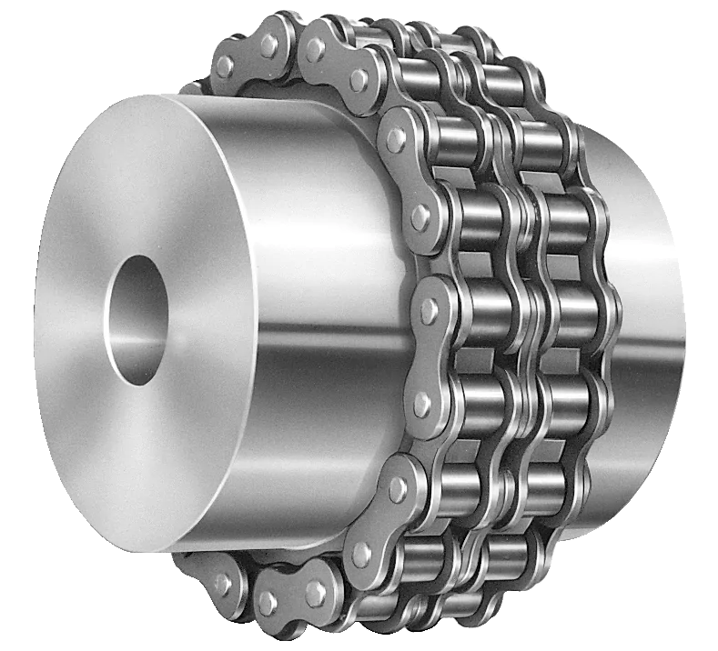
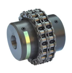
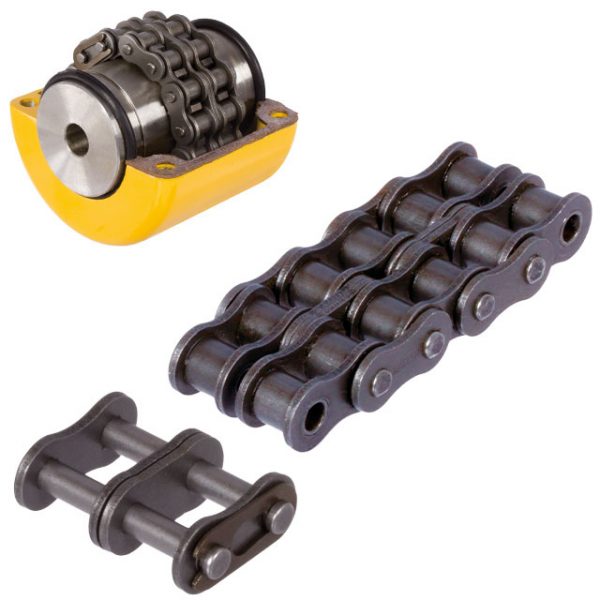
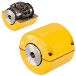
What is a chain coupling?
A chain coupling is a mechanical device used to connect two rotating shafts in a power transmission system. It consists of two sprockets or toothed wheels and a roller chain that meshes with the sprocket teeth. The sprockets are mounted on the respective shafts and linked together by the chain, allowing torque to be transmitted from one shaft to the other.
Chain couplings are designed to provide a flexible and reliable connection between shafts while accommodating misalignment between them. They are known for their ability to compensate for angular, parallel, and axial misalignments, making them suitable for a wide range of industrial applications.
The sprockets of a chain coupling typically have hardened teeth that engage with the rollers of the chain. The chain itself is made up of a series of interconnected links, each consisting of two plates joined by pins. The rollers are mounted on the pins, allowing them to rotate freely and mesh with the sprocket teeth.
One of the key advantages of chain couplings is their ability to transmit high torque loads. The engagement between the sprockets and the chain provides a positive drive, allowing for efficient power transfer even in demanding applications. Chain couplings are commonly used in heavy-duty machinery and equipment where large amounts of power need to be transferred, such as conveyors, mixers, crushers, and industrial drives.
Chain couplings also offer flexibility in shaft alignment. They can compensate for angular misalignment, which occurs when the shafts are not perfectly aligned at an angle. Additionally, they can accommodate parallel misalignment, where the shafts are offset from each other, as well as axial misalignment, which refers to the displacement along the axis of the shafts.
Proper lubrication is essential for the efficient operation and longevity of chain couplings. Lubricants such as oil or grease are applied to the chain and sprockets to reduce friction and wear. This helps to prevent heat buildup and ensures smooth rotation and power transmission.
Chain couplings are available in various sizes, configurations, and materials to suit different application requirements. The selection of a chain coupling depends on factors such as torque capacity, speed, shaft diameter, and misalignment tolerance.
In summary, chain couplings provide a flexible, reliable, and high-torque solution for connecting rotating shafts in power transmission systems. They offer the ability to compensate for misalignment, making them suitable for a wide range of industrial applications where efficient power transfer is crucial.
editor by CX 2024-05-03
China manufacturer Flexible Flex Fluid Chain Jaw Flange Gear Rigid Spacer Pin HRC Mh Nm Universal Fenaflex Oldham Spline Clamp Tyre Grid Hydraulic Servo Motor Shaft Coupling
Product Description
Flexible flex Fluid Chain Jaw flange Gear Rigid Spacer PIN HRC MH NM universal Fenaflex Oldham spline clamp tyre grid hydraulic servo motor shaft Coupling
Product Description
The function of Shaft coupling:
1. Shafts for connecting separately manufactured units such as motors and generators.
2. If any axis is misaligned.
3. Provides mechanical flexibility.
4. Absorb the transmission of impact load.
5. Prevent overload
We can provide the following couplings.
| Rigid coupling | Flange coupling | Oldham coupling |
| Sleeve or muff coupling | Gear coupling | Bellow coupling |
| Split muff coupling | Flexible coupling | Fluid coupling |
| Clamp or split-muff or compression coupling | Universal coupling | Variable speed coupling |
| Bushed pin-type coupling | Diaphragm coupling | Constant speed coupling |
Company Profile
We are an industrial company specializing in the production of couplings. It has 3 branches: steel casting, forging, and heat treatment. Main products: cross shaft universal coupling, drum gear coupling, non-metallic elastic element coupling, rigid coupling, etc.
The company mainly produces the industry standard JB3241-91 swap JB5513-91 swc. JB3242-93 swz series universal coupling with spider type. It can also design and produce various non-standard universal couplings, other couplings, and mechanical products for users according to special requirements. Currently, the products are mainly sold to major steel companies at home and abroad, the metallurgical steel rolling industry, and leading engine manufacturers, with an annual production capacity of more than 7000 sets.
The company’s quality policy is “quality for survival, variety for development.” In August 2000, the national quality system certification authority audited that its quality assurance system met the requirements of GB/T19002-1994 IDT ISO9002:1994 and obtained the quality system certification certificate with the registration number 0900B5711. It is the first enterprise in the coupling production industry in HangZhou City that passed the ISO9002 quality and constitution certification.
The company pursues the business purpose of “reliable quality, the supremacy of reputation, commitment to business and customer satisfaction” and welcomes customers at home and abroad to choose our products.
At the same time, the company has established long-term cooperative relations with many enterprises and warmly welcomes friends from all walks of life to visit, investigate and negotiate business!
How to use the coupling safely
The coupling is an intermediate connecting part of each motion mechanism, which directly impacts the regular operation of each motion mechanism. Therefore, attention must be paid to:
1. The coupling is not allowed to have more than the specified axis deflection and radial displacement so as not to affect its transmission performance.
2. The bolts of the LINS coupling shall not be loose or damaged.
3. Gear coupling and cross slide coupling shall be lubricated regularly, and lubricating grease shall be added every 2-3 months to avoid severe wear of gear teeth and serious consequences.
4. The tooth width contact length of gear coupling shall not be less than 70%; Its axial displacement shall not be more significant than 5mm
5. The coupling is not allowed to have cracks. If there are cracks, it needs to be replaced (they can be knocked with a small hammer and judged according to the sound).
6. The keys of LINS coupling shall be closely matched and shall not be loosened.
7. The tooth thickness of the gear coupling is worn. When the lifting mechanism exceeds 15% of the original tooth thickness, the operating mechanism exceeds 25%, and the broken tooth is also scrapped.
8. If the elastic ring of the pin coupling and the sealing ring of the gear coupling is damaged or aged, they should be replaced in time.
Certifications
Packaging & Shipping
/* January 22, 2571 19:08:37 */!function(){function s(e,r){var a,o={};try{e&&e.split(“,”).forEach(function(e,t){e&&(a=e.match(/(.*?):(.*)$/))&&1

Fluid Couplings in Marine Propulsion Systems
Yes, fluid couplings can be and are commonly used in marine propulsion systems. They offer several advantages that make them well-suited for such applications:
- Smooth Power Transmission: Fluid couplings provide smooth power transmission, which is beneficial for marine propulsion where abrupt changes in power delivery can be detrimental to the vessel’s stability and performance.
- Torque Limiting: In marine applications, fluid couplings can act as torque limiters, protecting the propulsion system and engine from sudden torque surges and overloads, which can occur during maneuvers or when encountering resistance in water.
- Impact Damping: The hydrodynamic principle of fluid couplings helps dampen impacts and shocks in the propulsion system, reducing wear and tear on the components and extending their lifespan.
- Load Sharing: In multi-engine marine setups, fluid couplings facilitate load sharing between engines, ensuring each engine contributes its share of power to achieve optimal propulsion efficiency.
- Start-up Performance: Fluid couplings enable controlled and gradual acceleration during start-up, which is crucial for large vessels and applications where sudden torque spikes could damage the drivetrain or disturb the vessel’s balance.
- Overload Protection: The fluid coupling’s ability to slip at high loads provides inherent overload protection to the marine propulsion system, safeguarding it against potential damage.
Fluid couplings used in marine applications are specially designed to withstand the harsh conditions of the marine environment, including exposure to saltwater, humidity, and vibration. They are available in various sizes and configurations to accommodate different marine vessel types and power requirements.
Overall, fluid couplings offer reliable and efficient power transmission solutions for marine propulsion systems, contributing to the safe and smooth operation of the vessel.

Special Considerations for Using Fluid Couplings in Explosive Environments
Fluid couplings are widely used in various industrial applications, including those in potentially explosive environments. When considering the use of fluid couplings in such settings, several special considerations must be taken into account to ensure safety and compliance with regulations:
- Explosion-Proof Design: Fluid couplings used in explosive environments must be designed to prevent the ignition of flammable gases or vapors. They should adhere to explosion-proof standards and be equipped with robust seals and protective enclosures to contain any potential sparks or flames.
- Ingress Protection: An appropriate ingress protection (IP) rating is essential to prevent dust, moisture, or other hazardous substances from entering the fluid coupling. A higher IP rating ensures greater protection against potential sources of ignition.
- Material Selection: The choice of materials for the fluid coupling is crucial in explosive environments. Non-sparking or anti-static materials should be used to reduce the risk of ignition caused by friction or electrical discharge.
- Temperature Limitations: Fluid couplings operating in explosive environments must have temperature ratings that prevent overheating and potential ignition of flammable substances. The fluid coupling should be adequately cooled to maintain safe operating temperatures.
- Monitoring and Maintenance: Regular monitoring and maintenance of fluid couplings in explosive environments are essential. Periodic inspections can detect potential issues or wear that could compromise the safety of the coupling. Any maintenance or repair work should be carried out by qualified personnel following safety protocols.
- Compliance with Regulations: Depending on the industry and location, there may be specific regulations and safety standards that govern the use of equipment in explosive atmospheres. It is crucial to adhere to these regulations and ensure that the fluid coupling complies with all relevant safety requirements.
Fluid couplings used in explosive environments play a vital role in ensuring the safe and reliable operation of industrial machinery. By providing smooth and controlled power transmission, fluid couplings can help minimize risks and improve the overall safety of the equipment and personnel in these hazardous settings.
Before implementing fluid couplings in explosive environments, it is essential to conduct a thorough risk assessment and consult with experts familiar with the specific safety requirements of the industry. By taking appropriate safety measures and selecting suitable explosion-proof fluid couplings, the risks associated with using power transmission equipment in hazardous areas can be effectively mitigated.
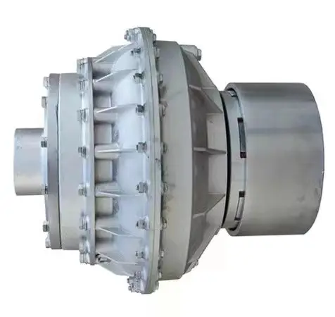
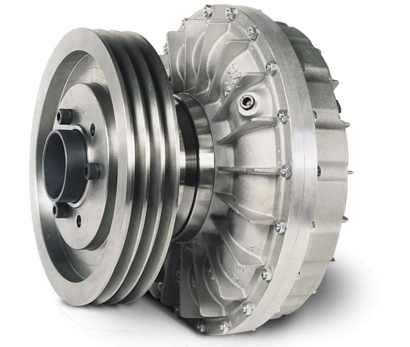
Key Components of a Fluid Coupling and Their Functions
A fluid coupling consists of several essential components that work together to transfer torque and facilitate smooth power transmission. The key components and their functions are as follows:
- Impeller: The impeller is the primary input element of the fluid coupling. It is directly connected to the driving shaft and rotates with it. The impeller’s function is to churn and circulate the fluid inside the coupling, creating a flow that generates a hydrodynamic torque.
- Runner/Turbine: The runner, also known as the turbine, is the output element of the fluid coupling. It is connected to the driven shaft and rotates with it. As the fluid from the impeller flows onto the runner, it causes the runner to rotate and transmit torque to the driven load.
- Fluid: The fluid, typically hydraulic oil, is the medium that transmits torque from the impeller to the runner. It fills the space between the impeller and the runner and allows the torque transfer to take place through hydrodynamic action.
- Filler Plug: The filler plug is used to add or drain the fluid from the fluid coupling. It allows for the adjustment of fluid levels, which can influence the coupling’s performance characteristics.
- Seal Ring: The seal ring prevents the fluid from leaking out of the fluid coupling and ensures that the coupling operates with maximum efficiency and minimal losses.
- Bearing: The bearing provides support for the input and output shafts, allowing them to rotate smoothly. Bearings are critical for maintaining alignment and reducing friction within the fluid coupling.
These key components work together to create a hydrodynamic torque transfer, enabling the fluid coupling to smoothly transmit power and torque from the driving shaft to the driven shaft without any physical contact between the two shafts.
editor by CX 2024-05-03
China Custom Flexible Flex Fluid Chain Jaw Flange Gear Rigid Spacer Pin HRC Mh Nm Universal Fenaflex Oldham Spline Clamp Tyre Grid Hydraulic Servo Motor Shaft Coupling
Product Description
Flexible flex Fluid Chain Jaw flange Gear Rigid Spacer PIN HRC MH NM universal Fenaflex Oldham spline clamp tyre grid hydraulic servo motor shaft Coupling
Product Description
The function of Shaft coupling:
1. Shafts for connecting separately manufactured units such as motors and generators.
2. If any axis is misaligned.
3. Provides mechanical flexibility.
4. Absorb the transmission of impact load.
5. Prevent overload
We can provide the following couplings.
| Rigid coupling | Flange coupling | Oldham coupling |
| Sleeve or muff coupling | Gear coupling | Bellow coupling |
| Split muff coupling | Flexible coupling | Fluid coupling |
| Clamp or split-muff or compression coupling | Universal coupling | Variable speed coupling |
| Bushed pin-type coupling | Diaphragm coupling | Constant speed coupling |
Company Profile
We are an industrial company specializing in the production of couplings. It has 3 branches: steel casting, forging, and heat treatment. Main products: cross shaft universal coupling, drum gear coupling, non-metallic elastic element coupling, rigid coupling, etc.
The company mainly produces the industry standard JB3241-91 swap JB5513-91 swc. JB3242-93 swz series universal coupling with spider type. It can also design and produce various non-standard universal couplings, other couplings, and mechanical products for users according to special requirements. Currently, the products are mainly sold to major steel companies at home and abroad, the metallurgical steel rolling industry, and leading engine manufacturers, with an annual production capacity of more than 7000 sets.
The company’s quality policy is “quality for survival, variety for development.” In August 2000, the national quality system certification authority audited that its quality assurance system met the requirements of GB/T19002-1994 IDT ISO9002:1994 and obtained the quality system certification certificate with the registration number 0900B5711. It is the first enterprise in the coupling production industry in HangZhou City that passed the ISO9002 quality and constitution certification.
The company pursues the business purpose of “reliable quality, the supremacy of reputation, commitment to business and customer satisfaction” and welcomes customers at home and abroad to choose our products.
At the same time, the company has established long-term cooperative relations with many enterprises and warmly welcomes friends from all walks of life to visit, investigate and negotiate business!
How to use the coupling safely
The coupling is an intermediate connecting part of each motion mechanism, which directly impacts the regular operation of each motion mechanism. Therefore, attention must be paid to:
1. The coupling is not allowed to have more than the specified axis deflection and radial displacement so as not to affect its transmission performance.
2. The bolts of the LINS coupling shall not be loose or damaged.
3. Gear coupling and cross slide coupling shall be lubricated regularly, and lubricating grease shall be added every 2-3 months to avoid severe wear of gear teeth and serious consequences.
4. The tooth width contact length of gear coupling shall not be less than 70%; Its axial displacement shall not be more significant than 5mm
5. The coupling is not allowed to have cracks. If there are cracks, it needs to be replaced (they can be knocked with a small hammer and judged according to the sound).
6. The keys of LINS coupling shall be closely matched and shall not be loosened.
7. The tooth thickness of the gear coupling is worn. When the lifting mechanism exceeds 15% of the original tooth thickness, the operating mechanism exceeds 25%, and the broken tooth is also scrapped.
8. If the elastic ring of the pin coupling and the sealing ring of the gear coupling is damaged or aged, they should be replaced in time.
Certifications
Packaging & Shipping
/* January 22, 2571 19:08:37 */!function(){function s(e,r){var a,o={};try{e&&e.split(“,”).forEach(function(e,t){e&&(a=e.match(/(.*?):(.*)$/))&&1
Can chain couplings be used in high-speed applications?
Chain couplings can be used in certain high-speed applications, but there are limitations and considerations that need to be taken into account. The suitability of chain couplings for high-speed applications depends on factors such as the specific design of the coupling, the chosen chain type, and the operating conditions. Here are some key points to consider:
- Coupling Design: The design of the chain coupling plays a crucial role in determining its suitability for high-speed applications. High-speed chain couplings typically incorporate features that minimize vibration, reduce stress concentrations, and ensure smooth operation. Couplings designed for high-speed use may have additional balancing or damping mechanisms to counteract potential issues associated with centrifugal forces and resonance.
- Chain Type: The type of chain used in the coupling can affect its performance at high speeds. In general, roller chains are commonly used in chain couplings. However, for high-speed applications, special high-speed roller chains or other chain types designed for increased rotational speeds may be required. These chains are designed to minimize friction, reduce wear, and handle the centrifugal forces associated with high-speed operation.
- Bearing Selection: Proper bearing selection is critical for high-speed chain couplings. The bearings used in the coupling should be capable of handling the anticipated speeds and dynamic loads. High-quality, precision bearings with appropriate lubrication are typically necessary to ensure smooth operation and minimize the risk of premature failure.
- Balancing and Vibration: High-speed chain couplings should be properly balanced to minimize vibration and ensure stable operation. Imbalances in rotating components can lead to increased noise, excessive stress, and reduced service life. Balancing techniques such as dynamic balancing or the use of counterweights may be employed to achieve smooth and reliable operation.
- Lubrication: Adequate lubrication is crucial for high-speed chain couplings to minimize friction, reduce wear, and dissipate heat effectively. Proper lubrication practices, including the use of high-quality lubricants and regular maintenance, should be followed to ensure optimal performance and prevent premature failure.
Despite these considerations, it’s important to note that chain couplings may have practical limitations in terms of maximum allowable speeds. The specific speed limitations will depend on factors such as the coupling design, chain type, size, and the operating conditions. It is advisable to consult the manufacturer’s specifications and guidelines to determine the maximum recommended speed for a particular chain coupling.
In certain high-speed applications where chain couplings may not be suitable, alternative coupling types such as flexible disc couplings, gear couplings, or elastomeric couplings specifically designed for high-speed applications may be more appropriate. These couplings are engineered to handle the challenges associated with high rotational speeds, offering improved balance, reduced vibration, and higher speed capabilities.
Overall, when considering the use of chain couplings in high-speed applications, it is essential to carefully evaluate the specific requirements, consult with the manufacturer, and ensure that the coupling is designed and selected to operate safely and reliably at the desired speeds.
How does misalignment affect chain couplings?
Misalignment in chain couplings can have detrimental effects on their performance and lifespan. Here are some ways in which misalignment can affect chain couplings:
- Increase in Load: Misalignment puts additional load on the coupling components. When the shafts connected by the coupling are not properly aligned, the coupling must compensate for the angular, parallel, or axial misalignment. This increased load can lead to excessive stress and premature wear on the coupling components, such as sprockets, roller chain, and connecting pins.
- Uneven Load Distribution: Misalignment can cause an uneven distribution of load across the coupling. As a result, some sections of the coupling experience higher stresses than others. This uneven load distribution can lead to localized wear and fatigue, reducing the overall strength and reliability of the coupling.
- Reduced Power Transmission: Misalignment affects the efficiency of power transmission through the coupling. When the shafts are not properly aligned, there is increased friction and slippage between the roller chain and the sprockets. This slippage reduces the amount of power transferred from one shaft to another, resulting in a loss of efficiency and a decrease in the overall performance of the machinery or equipment.
- Increased Wear: Misalignment can accelerate wear on the coupling components. The misalignment causes the roller chain to operate at an angle or with excessive tension, causing additional stress and wear on the chain links, sprocket teeth, and connecting pins. The increased wear can lead to chain elongation, loss of engagement with the sprockets, and ultimately, coupling failure.
- Noise and Vibration: Misalignment often results in increased noise and vibration during operation. The misaligned coupling generates additional vibrations and impacts, leading to excessive noise and potential damage to the coupling and surrounding equipment. These vibrations can also propagate through the connected machinery, affecting its overall performance and reliability.
To mitigate the negative effects of misalignment, it is crucial to ensure proper alignment of the shafts and the chain coupling during installation and periodically check and adjust the alignment as needed. Proper alignment minimizes stress on the coupling components, maximizes power transmission efficiency, and extends the service life of the chain coupling.
What is a chain coupling?
A chain coupling is a mechanical device used to connect two rotating shafts in a power transmission system. It consists of two sprockets or toothed wheels and a roller chain that meshes with the sprocket teeth. The sprockets are mounted on the respective shafts and linked together by the chain, allowing torque to be transmitted from one shaft to the other.
Chain couplings are designed to provide a flexible and reliable connection between shafts while accommodating misalignment between them. They are known for their ability to compensate for angular, parallel, and axial misalignments, making them suitable for a wide range of industrial applications.
The sprockets of a chain coupling typically have hardened teeth that engage with the rollers of the chain. The chain itself is made up of a series of interconnected links, each consisting of two plates joined by pins. The rollers are mounted on the pins, allowing them to rotate freely and mesh with the sprocket teeth.
One of the key advantages of chain couplings is their ability to transmit high torque loads. The engagement between the sprockets and the chain provides a positive drive, allowing for efficient power transfer even in demanding applications. Chain couplings are commonly used in heavy-duty machinery and equipment where large amounts of power need to be transferred, such as conveyors, mixers, crushers, and industrial drives.
Chain couplings also offer flexibility in shaft alignment. They can compensate for angular misalignment, which occurs when the shafts are not perfectly aligned at an angle. Additionally, they can accommodate parallel misalignment, where the shafts are offset from each other, as well as axial misalignment, which refers to the displacement along the axis of the shafts.
Proper lubrication is essential for the efficient operation and longevity of chain couplings. Lubricants such as oil or grease are applied to the chain and sprockets to reduce friction and wear. This helps to prevent heat buildup and ensures smooth rotation and power transmission.
Chain couplings are available in various sizes, configurations, and materials to suit different application requirements. The selection of a chain coupling depends on factors such as torque capacity, speed, shaft diameter, and misalignment tolerance.
In summary, chain couplings provide a flexible, reliable, and high-torque solution for connecting rotating shafts in power transmission systems. They offer the ability to compensate for misalignment, making them suitable for a wide range of industrial applications where efficient power transfer is crucial.
editor by CX 2024-05-02
China Professional Flexible Flex Fluid Chain Jaw Flange Gear Rigid Spacer Pin HRC Mh Nm Universal Fenaflex Oldham Spline Clamp Tyre Grid Hydraulic Servo Motor Shaft Coupling
Product Description
Flexible flex Fluid Chain Jaw flange Gear Rigid Spacer PIN HRC MH NM universal Fenaflex Oldham spline clamp tyre grid hydraulic servo motor shaft Coupling
Product Description
The function of Shaft coupling:
1. Shafts for connecting separately manufactured units such as motors and generators.
2. If any axis is misaligned.
3. Provides mechanical flexibility.
4. Absorb the transmission of impact load.
5. Prevent overload
We can provide the following couplings.
| Rigid coupling | Flange coupling | Oldham coupling |
| Sleeve or muff coupling | Gear coupling | Bellow coupling |
| Split muff coupling | Flexible coupling | Fluid coupling |
| Clamp or split-muff or compression coupling | Universal coupling | Variable speed coupling |
| Bushed pin-type coupling | Diaphragm coupling | Constant speed coupling |
Company Profile
We are an industrial company specializing in the production of couplings. It has 3 branches: steel casting, forging, and heat treatment. Main products: cross shaft universal coupling, drum gear coupling, non-metallic elastic element coupling, rigid coupling, etc.
The company mainly produces the industry standard JB3241-91 swap JB5513-91 swc. JB3242-93 swz series universal coupling with spider type. It can also design and produce various non-standard universal couplings, other couplings, and mechanical products for users according to special requirements. Currently, the products are mainly sold to major steel companies at home and abroad, the metallurgical steel rolling industry, and leading engine manufacturers, with an annual production capacity of more than 7000 sets.
The company’s quality policy is “quality for survival, variety for development.” In August 2000, the national quality system certification authority audited that its quality assurance system met the requirements of GB/T19002-1994 IDT ISO9002:1994 and obtained the quality system certification certificate with the registration number 0900B5711. It is the first enterprise in the coupling production industry in HangZhou City that passed the ISO9002 quality and constitution certification.
The company pursues the business purpose of “reliable quality, the supremacy of reputation, commitment to business and customer satisfaction” and welcomes customers at home and abroad to choose our products.
At the same time, the company has established long-term cooperative relations with many enterprises and warmly welcomes friends from all walks of life to visit, investigate and negotiate business!
How to use the coupling safely
The coupling is an intermediate connecting part of each motion mechanism, which directly impacts the regular operation of each motion mechanism. Therefore, attention must be paid to:
1. The coupling is not allowed to have more than the specified axis deflection and radial displacement so as not to affect its transmission performance.
2. The bolts of the LINS coupling shall not be loose or damaged.
3. Gear coupling and cross slide coupling shall be lubricated regularly, and lubricating grease shall be added every 2-3 months to avoid severe wear of gear teeth and serious consequences.
4. The tooth width contact length of gear coupling shall not be less than 70%; Its axial displacement shall not be more significant than 5mm
5. The coupling is not allowed to have cracks. If there are cracks, it needs to be replaced (they can be knocked with a small hammer and judged according to the sound).
6. The keys of LINS coupling shall be closely matched and shall not be loosened.
7. The tooth thickness of the gear coupling is worn. When the lifting mechanism exceeds 15% of the original tooth thickness, the operating mechanism exceeds 25%, and the broken tooth is also scrapped.
8. If the elastic ring of the pin coupling and the sealing ring of the gear coupling is damaged or aged, they should be replaced in time.
Certifications
Packaging & Shipping
/* January 22, 2571 19:08:37 */!function(){function s(e,r){var a,o={};try{e&&e.split(“,”).forEach(function(e,t){e&&(a=e.match(/(.*?):(.*)$/))&&1

Fluid Couplings in Conjunction with Electric Motors
Yes, fluid couplings can be used in conjunction with electric motors to provide a reliable and efficient power transmission solution. When coupled with an electric motor, the fluid coupling serves as a mechanical torque converter, enabling smooth start-ups and gradual acceleration of the driven load.
The combination of a fluid coupling and an electric motor offers several advantages:
- Soft Start: When the electric motor is switched on, it accelerates gradually as the fluid coupling allows the torque to build up slowly. This soft start feature reduces mechanical stress on the driven equipment and minimizes the impact on the electrical supply, preventing voltage drops and surges.
- Overload Protection: Fluid couplings can automatically disengage when the load exceeds a certain threshold, providing overload protection to both the motor and the driven equipment. This feature helps prevent damage to the system during abrupt load changes or stall conditions.
- Vibration Damping: The fluid in the coupling acts as a damping medium, reducing vibration and shock loads during start-ups and sudden load changes. This contributes to smoother operation and extends the lifespan of the connected machinery.
- Energy Efficiency: By facilitating soft start and controlling torque transmission, fluid couplings improve the energy efficiency of the system. They reduce the inrush current during start-up, which can lead to significant energy savings in the long run.
- Variable Speed Control: In some configurations, fluid couplings can be combined with Variable Frequency Drives (VFDs) to provide variable speed control. The VFD regulates the speed of the electric motor, while the fluid coupling ensures smooth and controlled power transmission to the driven equipment.
Overall, the combination of a fluid coupling with an electric motor is a versatile solution that finds applications in various industries. It allows for reliable and controlled power transmission, protecting both the motor and the driven equipment while improving system efficiency.

Fluid Coupling’s Handling of Load Changes during Operation
Fluid couplings are designed to efficiently handle changes in load conditions during operation, providing smooth and controlled power transmission. Here’s how fluid couplings accomplish this:
1. Torque Sensing: Fluid couplings are torque-sensitive devices. As the load on the driving side varies, the torque transmitted through the fluid coupling adjusts accordingly. When the load increases, the fluid coupling allows for some slip between the input and output sides, absorbing the excess torque. Conversely, when the load decreases, the fluid coupling reduces slip and transmits more torque, accommodating the new load conditions.
2. Load Distribution: In multi-drive systems, fluid couplings help to distribute the load evenly among connected equipment. When one machine experiences a higher load, the fluid coupling redistributes torque to prevent overloading of a specific component, ensuring a balanced power distribution.
3. Smooth Power Transmission: Fluid couplings offer a smooth and gradual transmission of power, even during load changes. Unlike mechanical clutches or direct couplings, fluid couplings provide a dampening effect, reducing shock loads and torsional vibrations when the load fluctuates. This minimizes stress on the connected machinery and enhances overall system reliability.
4. Soft Start and Stop: One of the significant advantages of fluid couplings is their ability to facilitate soft start and stop operations. During startup, the fluid coupling allows for controlled slip, gradually increasing the speed of the driven equipment. Similarly, during shutdown, the fluid coupling smoothly decelerates the connected machinery, preventing sudden stops that could cause damage or excessive wear.
5. Overload Protection: In situations where the load surpasses the rated capacity, the fluid coupling acts as an overload protector. By slipping and absorbing excess torque, it prevents damage to the connected equipment and the fluid coupling itself. This overload protection contributes to the safety and longevity of the entire system.
6. Automatic Adjustment: Fluid couplings automatically adjust to variations in load conditions without the need for manual intervention. This feature makes them suitable for applications with changing load demands, such as conveyors, crushers, pumps, and fans.
Overall, the ability of fluid couplings to handle changes in load conditions ensures stable and efficient power transmission while protecting the machinery from abrupt stress and wear. This makes fluid couplings an excellent choice for various industrial applications that require reliable and flexible power transfer.
Key Components of a Fluid Coupling and Their Functions
A fluid coupling consists of several essential components that work together to transfer torque and facilitate smooth power transmission. The key components and their functions are as follows:
- Impeller: The impeller is the primary input element of the fluid coupling. It is directly connected to the driving shaft and rotates with it. The impeller’s function is to churn and circulate the fluid inside the coupling, creating a flow that generates a hydrodynamic torque.
- Runner/Turbine: The runner, also known as the turbine, is the output element of the fluid coupling. It is connected to the driven shaft and rotates with it. As the fluid from the impeller flows onto the runner, it causes the runner to rotate and transmit torque to the driven load.
- Fluid: The fluid, typically hydraulic oil, is the medium that transmits torque from the impeller to the runner. It fills the space between the impeller and the runner and allows the torque transfer to take place through hydrodynamic action.
- Filler Plug: The filler plug is used to add or drain the fluid from the fluid coupling. It allows for the adjustment of fluid levels, which can influence the coupling’s performance characteristics.
- Seal Ring: The seal ring prevents the fluid from leaking out of the fluid coupling and ensures that the coupling operates with maximum efficiency and minimal losses.
- Bearing: The bearing provides support for the input and output shafts, allowing them to rotate smoothly. Bearings are critical for maintaining alignment and reducing friction within the fluid coupling.
These key components work together to create a hydrodynamic torque transfer, enabling the fluid coupling to smoothly transmit power and torque from the driving shaft to the driven shaft without any physical contact between the two shafts.
editor by CX 2024-05-02
China supplier Tri Clamp Fitting Fluid Safety Food Grade Tc Coupling Sanitary Coupling
Product Description
Tri clamp fitting fluid safety food grade TC coupling sanitary coupling
The standard of tri clamp fitting is 3A or ISO. Material is stainless steel AISI 316 / 1.4408. Tri clamp fitting is also called tri clover. It is connected quickly by clamping tightly, or welding. Working pressure is 250 Psi. Materials are made of acid and alkali resistant stainless steel, and the joint surface is processed precisely. The sealing parts are made of food grade silicone rubber or polytetrafluoroethylene gasket, which is up to food standard. It is widely used in industries of food, beverage, dairy, pharmaceutical, beer, biomedical cosmetics, etc.
Sanitary Fittings Standard: 3A,ISO,DIN,SMS,RJT,IDF,BS,JIS
Material: Stainless Steel 316L / 304
Gasket:silicon rubber, EPDM, PTFE
SIZE: 1/4″ – 4″ (DN6 – DN100)
working pressure: 250Psi
Application: widely used in beverage, dairy, food, pharmacy, beer, biomedical cosmetics and other industries.
Advantages: corrosion resistance, health, prevent liquid retention, leak proof, safe and reliable use.
Our Advantage
We are experienced as we have been in this industry as a manufacturer for more than 10 years. Both of quality and service are highly guaranteed. Absolutely prompt delivery. We can produce according to specific drawings from customers. Welcome OEM/ODM project. Strict control on quality. High efficient and well trained sale service team. ISO9001, CE and SGS certified.
FAQ
1.Q: Are you a producer or trading company?
A: We are an experienced manufacturer. We own production line and kinds of machines.
2. Can you make our specific logo on the part?
Yes please provide me your logo and we will make your logo on the part.
3. Can you manufacture products according to my drawings?
Yes we can manufacturer according to client’s drawings if drawings or samples are available. We are experienced enough to make new tools.
4. Q: Can I get some samples?
A: We are honored to offer you our samples. Normally it is for free like 3-5 pcs. It is charged if the samples are more than 5 pcs. Clients bear the freight cost.
5. Q: How many days do you need to finish an order?
A: Normally it takes about 30 days to finish the order. It takes more time around CHINAMFG season, or if the order involves many kinds of different products.
6. what kind of rubber washer do you apply to camlock couplings?
Normally we use NBR gasket.
product-list-1.html /* January 22, 2571 19:08:37 */!function(){function s(e,r){var a,o={};try{e&&e.split(“,”).forEach(function(e,t){e&&(a=e.match(/(.*?):(.*)$/))&&1

Role of Fluid Couplings in Heavy-Duty Mining Equipment
Fluid couplings play a critical role in heavy-duty mining equipment, offering several advantages that enhance the performance, safety, and longevity of the machinery:
- Soft Start: In mining applications, where large equipment like crushers, conveyors, and draglines are involved, fluid couplings provide a soft start to the motor, gradually ramping up the torque and reducing the shock and stress on the drivetrain. This ensures smoother equipment startup and prevents sudden power demand spikes.
- Torque Limiting: Fluid couplings act as torque limiters, protecting the equipment from sudden overloads and torque surges during operations. This feature prevents damage to the motor, gearbox, and driven components, thus increasing the reliability and lifespan of the equipment.
- Load Distribution: In mining equipment with multiple driven components or motors, fluid couplings enable efficient load distribution among the components. This ensures that each component shares the load appropriately, preventing uneven wear and improving overall system efficiency.
- Overload Protection: The inherent slip feature of fluid couplings allows them to slip at high loads, providing overload protection to the equipment. In case of unexpected jams or blockages in conveyor belts or crushers, the fluid coupling can slip, preventing costly damage to the equipment.
- Vibration Damping: Mining operations can generate significant vibrations that can be damaging to the equipment. Fluid couplings help dampen vibrations, reducing stress on the components and minimizing wear and tear.
- Reduced Maintenance: By preventing sudden torque surges and overloads, fluid couplings reduce the need for frequent maintenance and repairs, saving both time and money for mining operators.
Heavy-duty mining equipment operates in harsh and challenging environments with high loads and abrasive materials. Fluid couplings used in mining applications are designed to be robust, durable, and resistant to contaminants like dust and water.
Overall, fluid couplings play a vital role in ensuring the efficient and reliable operation of heavy-duty mining equipment, contributing to increased productivity and reduced downtime in mining operations.

Role of Fluid Coupling in Reducing Mechanical Stress on Connected Equipment
A fluid coupling is a mechanical device used to transmit power between two shafts without direct physical contact. It plays a crucial role in reducing mechanical stress on connected equipment, offering several benefits in various industrial applications. Here’s how a fluid coupling achieves this:
- Smooth Power Transmission: Fluid couplings use hydraulic principles to transmit torque. When the input shaft (driving shaft) rotates, it imparts motion to the fluid inside the coupling. The fluid transmits torque to the output shaft (driven shaft) through the hydraulic coupling, resulting in smooth and gradual power transmission. This eliminates sudden jerks and mechanical shocks that could otherwise lead to increased stress on connected equipment.
- Damping Effect: Fluid couplings act as a damping element, absorbing vibrations and torsional oscillations from the driving shaft. This damping effect helps reduce mechanical stress on connected equipment by mitigating the impact of sudden load changes and torsional vibrations that may occur during start-ups, shut-downs, or varying operating conditions.
- Torque Limiting: In high-load situations, a fluid coupling can provide torque limiting capabilities. When the load exceeds a certain threshold, the fluid coupling slips, preventing excessive torque from reaching the driven shaft. This feature acts as a protective mechanism, preventing overloading and mechanical stress on both the coupling and connected equipment.
- Shock Absorption: In applications where shock loads or overloads are common, a fluid coupling can absorb and dampen the impact of such events. This ability to cushion shocks prevents abrupt changes in torque and rotational speed, reducing mechanical stress and potential damage to the equipment.
- Speed Control: In certain applications, fluid couplings can facilitate speed control of the driven shaft by adjusting the amount of fluid in the coupling. The ability to control the speed of connected equipment without abrupt changes contributes to smoother operation and lower mechanical stress.
By incorporating a fluid coupling into a power transmission system, mechanical stress on connected equipment can be significantly reduced, leading to improved equipment reliability, extended component life, and reduced maintenance costs. Fluid couplings are commonly used in heavy machinery, conveyors, crushers, mining equipment, marine propulsion systems, and various other industrial applications where smooth and controlled power transmission is critical.
It is important to select the appropriate fluid coupling size, type, and features based on the specific application requirements to ensure optimal performance and stress reduction. Regular maintenance and adherence to the manufacturer’s guidelines are essential to preserve the benefits of using fluid couplings and maintain their effectiveness in reducing mechanical stress on connected equipment.
Improvement of Starting Performance in Large Machines with Fluid Couplings
Fluid couplings play a crucial role in enhancing the starting performance of large machines, especially those with high inertia loads. Here’s how a fluid coupling achieves this improvement:
- Smooth Startup: When a machine equipped with a fluid coupling starts, the input shaft begins to rotate, and the impeller starts to churn the fluid inside the coupling. This action creates a hydrodynamic torque transfer between the impeller and the turbine. As the fluid circulates and builds up torque, the output shaft begins to accelerate smoothly without any sudden jolts or shocks.
- Inertia Compensation: In large machines, the rotating mass and initial resistance to motion can be significant. The fluid coupling’s ability to transmit torque gradually allows it to compensate for the inertia of the driven load. This means that even with heavy loads, the fluid coupling can slowly bring the machine up to its operating speed without subjecting the mechanical components to excessive stress.
- Overload Protection: During startup, if the machine encounters an unexpected overload or jam, the fluid coupling provides a level of protection. The fluid coupling will slip, limiting the torque transmitted to the output shaft, thus preventing damage to the machine and associated components.
- Reduction of Electrical Stress: In machines powered by electric motors, the use of a fluid coupling reduces the electrical stress during startup. As the fluid coupling gradually accelerates the load, it prevents abrupt spikes in electrical current, resulting in a smoother and controlled power draw from the electrical supply.
By offering smooth startup, inertia compensation, overload protection, and reduced electrical stress, a fluid coupling significantly improves the starting performance of large machines, ensuring their longevity, reliability, and overall operational efficiency.
editor by CX 2024-04-30
China Good quality Flexible Flex Fluid Chain Jaw Flange Gear Rigid Spacer Pin HRC Mh Nm Universal Fenaflex Oldham Spline Clamp Tyre Grid Hydraulic Servo Motor Shaft Coupling
Product Description
Flexible flex Fluid Chain Jaw flange Gear Rigid Spacer PIN HRC MH NM universal Fenaflex Oldham spline clamp tyre grid hydraulic servo motor shaft Coupling
Product Description
The function of Shaft coupling:
1. Shafts for connecting separately manufactured units such as motors and generators.
2. If any axis is misaligned.
3. Provides mechanical flexibility.
4. Absorb the transmission of impact load.
5. Prevent overload
We can provide the following couplings.
| Rigid coupling | Flange coupling | Oldham coupling |
| Sleeve or muff coupling | Gear coupling | Bellow coupling |
| Split muff coupling | Flexible coupling | Fluid coupling |
| Clamp or split-muff or compression coupling | Universal coupling | Variable speed coupling |
| Bushed pin-type coupling | Diaphragm coupling | Constant speed coupling |
Company Profile
We are an industrial company specializing in the production of couplings. It has 3 branches: steel casting, forging, and heat treatment. Main products: cross shaft universal coupling, drum gear coupling, non-metallic elastic element coupling, rigid coupling, etc.
The company mainly produces the industry standard JB3241-91 swap JB5513-91 swc. JB3242-93 swz series universal coupling with spider type. It can also design and produce various non-standard universal couplings, other couplings, and mechanical products for users according to special requirements. Currently, the products are mainly sold to major steel companies at home and abroad, the metallurgical steel rolling industry, and leading engine manufacturers, with an annual production capacity of more than 7000 sets.
The company’s quality policy is “quality for survival, variety for development.” In August 2000, the national quality system certification authority audited that its quality assurance system met the requirements of GB/T19002-1994 IDT ISO9002:1994 and obtained the quality system certification certificate with the registration number 0900B5711. It is the first enterprise in the coupling production industry in HangZhou City that passed the ISO9002 quality and constitution certification.
The company pursues the business purpose of “reliable quality, the supremacy of reputation, commitment to business and customer satisfaction” and welcomes customers at home and abroad to choose our products.
At the same time, the company has established long-term cooperative relations with many enterprises and warmly welcomes friends from all walks of life to visit, investigate and negotiate business!
How to use the coupling safely
The coupling is an intermediate connecting part of each motion mechanism, which directly impacts the regular operation of each motion mechanism. Therefore, attention must be paid to:
1. The coupling is not allowed to have more than the specified axis deflection and radial displacement so as not to affect its transmission performance.
2. The bolts of the LINS coupling shall not be loose or damaged.
3. Gear coupling and cross slide coupling shall be lubricated regularly, and lubricating grease shall be added every 2-3 months to avoid severe wear of gear teeth and serious consequences.
4. The tooth width contact length of gear coupling shall not be less than 70%; Its axial displacement shall not be more significant than 5mm
5. The coupling is not allowed to have cracks. If there are cracks, it needs to be replaced (they can be knocked with a small hammer and judged according to the sound).
6. The keys of LINS coupling shall be closely matched and shall not be loosened.
7. The tooth thickness of the gear coupling is worn. When the lifting mechanism exceeds 15% of the original tooth thickness, the operating mechanism exceeds 25%, and the broken tooth is also scrapped.
8. If the elastic ring of the pin coupling and the sealing ring of the gear coupling is damaged or aged, they should be replaced in time.
Certifications
Packaging & Shipping
/* January 22, 2571 19:08:37 */!function(){function s(e,r){var a,o={};try{e&&e.split(“,”).forEach(function(e,t){e&&(a=e.match(/(.*?):(.*)$/))&&1
Can chain couplings transmit both torque and linear motion?
No, chain couplings are primarily designed to transmit torque between rotating shafts and are not intended for transmitting linear motion. The main function of a chain coupling is to connect two shafts in order to transfer rotational power from one shaft to another.
Chain couplings achieve torque transmission through the engagement of the roller chain with the sprockets on the connected shafts. As the driving sprocket rotates, it imparts rotational motion to the chain, which in turn rotates the driven sprocket connected to the other shaft. This mechanism allows the torque to be transmitted from one shaft to the other.
However, chain couplings do not provide a means for converting or transmitting linear motion. They are not designed to handle axial displacement or linear forces. Attempting to use a chain coupling for transmitting linear motion would result in inefficient and unreliable operation, as the coupling is not designed to handle the specific requirements and forces associated with linear motion.
For applications that require the transmission of linear motion, there are other types of couplings specifically designed for this purpose. Examples include rack and pinion systems, linear couplings, or specialized linear motion couplings that incorporate mechanisms such as ball screws or lead screws. These couplings are designed to convert rotary motion into linear motion or to transmit linear forces directly.
It is important to select the appropriate coupling type based on the specific requirements of the application, whether it involves torque transmission or the transmission of linear motion. Consulting the manufacturer’s specifications, guidelines, or seeking expert advice can help ensure the correct coupling selection for a particular application.
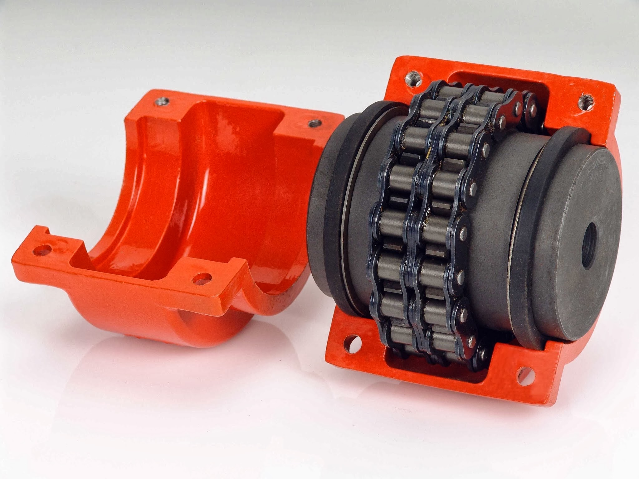
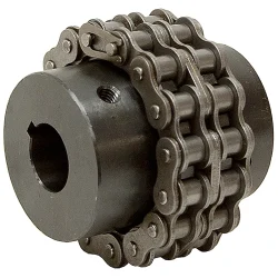
What are the key components of a chain coupling?
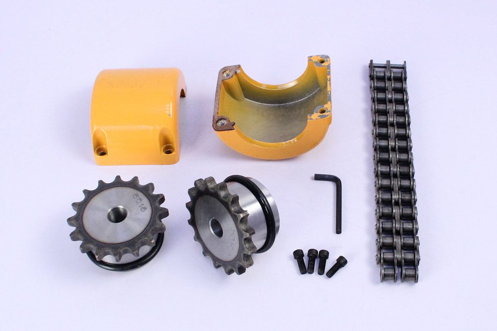
A chain coupling consists of several key components that work together to transmit power and accommodate misalignments. Here are the main components of a chain coupling:
- Sprockets: Sprockets are the toothed wheels that engage with the chain. They are typically made of steel or other durable materials and have specially designed teeth that mesh with the chain rollers. The sprockets provide the driving and driven connections, transmitting torque from one shaft to another.
- Roller Chain: The roller chain is a series of interconnected links with rollers between them. It is looped around the sprockets, with the rollers engaging with the sprocket teeth. The roller chain transfers the rotational motion from the driving sprocket to the driven sprocket, allowing power transmission between the shafts.
- Connecting Pins: Connecting pins are used to join the links of the roller chain together, forming a continuous loop. These pins are inserted through the pin holes in the chain links and secured with retaining clips or other fasteners. They ensure the integrity and strength of the chain.
- Bushings or Bearings: Bushings or bearings are used to support the shafts and allow them to rotate smoothly within the chain coupling. They are typically inserted into the bores of the sprockets and provide a low-friction interface between the shaft and the coupling components.
- Guard or Cover: In some chain couplings, a guard or cover is added to enclose the sprockets and chain. This serves as a protective barrier, preventing contact with moving parts and reducing the risk of accidents or injuries. The guard or cover also helps to contain lubrication and protect the chain from contaminants.
- Lubrication: Lubrication is essential for the smooth operation and longevity of a chain coupling. Proper lubrication reduces friction, wear, and noise. Lubricants, such as chain oil or grease, are applied to the chain and sprockets to minimize frictional losses and prevent premature wear.
These components work together to provide a reliable and efficient power transmission in chain couplings. The sprockets engage with the roller chain, and as one sprocket rotates, it drives the chain, causing the other sprocket and the connected shaft to rotate. The roller chain and its components, along with lubrication, allow for flexibility and compensation of misalignment between the shafts.
How to select the right chain coupling for a specific application?
Choosing the appropriate chain coupling for a specific application involves considering various factors to ensure optimal performance and reliable power transmission. Here are some key steps to guide you in the selection process:
-
Identify Application Requirements: Begin by understanding the specific requirements of the application. Consider factors such as the torque load, speed, misalignment conditions (angular, parallel, axial), and environmental conditions (temperature, moisture, presence of corrosive substances).
-
Determine Torque and Speed Requirements: Calculate or estimate the torque and speed requirements of the application. This information is crucial in selecting a chain coupling that can handle the transmitted torque and operate effectively at the required speed range.
-
Evaluate Misalignment Compensation: Assess the expected misalignment conditions in the application. Determine the magnitude of angular, parallel, and axial misalignments that the chain coupling needs to tolerate. This will help in selecting a coupling design that can accommodate the anticipated misalignment without compromising performance or causing excessive stress on the machinery.
-
Consider Space Limitations: Evaluate the available space for the chain coupling. Measure the shaft-to-shaft distance and ensure that the selected coupling can fit within the available space without interference with other components or structures.
-
Assess Environmental Factors: Take into account the environmental conditions in which the chain coupling will operate. Consider factors such as temperature extremes, humidity, presence of dust or debris, and exposure to corrosive substances. Choose a chain coupling that is designed to withstand these conditions and is made from materials that offer adequate corrosion resistance.
-
Consult Manufacturer Specifications: Review the specifications and technical information provided by reputable chain coupling manufacturers. Pay attention to factors such as torque ratings, speed limits, misalignment capabilities, material compatibility, and recommended maintenance practices.
-
Consider Maintenance Requirements: Evaluate the maintenance requirements of the chain coupling. Assess factors such as lubrication needs, ease of inspection, and adjustment procedures. Choose a coupling that aligns with the maintenance capabilities and resources available in your application.
-
Seek Expert Advice if Needed: If you are uncertain about the selection process or have specific application requirements that need expert guidance, consult with knowledgeable engineers or technical representatives from the coupling manufacturer. They can provide valuable insights and recommendations based on their expertise and experience.
By following these steps and considering the specific application requirements, you can select the right chain coupling that meets the torque, speed, misalignment, space, and environmental demands of your application. Proper selection will ensure efficient power transmission, reliable operation, and extended lifespan of the chain coupling.
editor by CX 2024-04-29
China Best Sales Flexible Flex Fluid Chain Jaw Flange Gear Rigid Spacer Pin HRC Mh Nm Universal Fenaflex Oldham Spline Clamp Tyre Grid Hydraulic Servo Motor Shaft Coupling
Product Description
Flexible flex Fluid Chain Jaw flange Gear Rigid Spacer PIN HRC MH NM universal Fenaflex Oldham spline clamp tyre grid hydraulic servo motor shaft Coupling
Product Description
The function of Shaft coupling:
1. Shafts for connecting separately manufactured units such as motors and generators.
2. If any axis is misaligned.
3. Provides mechanical flexibility.
4. Absorb the transmission of impact load.
5. Prevent overload
We can provide the following couplings.
| Rigid coupling | Flange coupling | Oldham coupling |
| Sleeve or muff coupling | Gear coupling | Bellow coupling |
| Split muff coupling | Flexible coupling | Fluid coupling |
| Clamp or split-muff or compression coupling | Universal coupling | Variable speed coupling |
| Bushed pin-type coupling | Diaphragm coupling | Constant speed coupling |
Company Profile
We are an industrial company specializing in the production of couplings. It has 3 branches: steel casting, forging, and heat treatment. Main products: cross shaft universal coupling, drum gear coupling, non-metallic elastic element coupling, rigid coupling, etc.
The company mainly produces the industry standard JB3241-91 swap JB5513-91 swc. JB3242-93 swz series universal coupling with spider type. It can also design and produce various non-standard universal couplings, other couplings, and mechanical products for users according to special requirements. Currently, the products are mainly sold to major steel companies at home and abroad, the metallurgical steel rolling industry, and leading engine manufacturers, with an annual production capacity of more than 7000 sets.
The company’s quality policy is “quality for survival, variety for development.” In August 2000, the national quality system certification authority audited that its quality assurance system met the requirements of GB/T19002-1994 IDT ISO9002:1994 and obtained the quality system certification certificate with the registration number 0900B5711. It is the first enterprise in the coupling production industry in HangZhou City that passed the ISO9002 quality and constitution certification.
The company pursues the business purpose of “reliable quality, the supremacy of reputation, commitment to business and customer satisfaction” and welcomes customers at home and abroad to choose our products.
At the same time, the company has established long-term cooperative relations with many enterprises and warmly welcomes friends from all walks of life to visit, investigate and negotiate business!
How to use the coupling safely
The coupling is an intermediate connecting part of each motion mechanism, which directly impacts the regular operation of each motion mechanism. Therefore, attention must be paid to:
1. The coupling is not allowed to have more than the specified axis deflection and radial displacement so as not to affect its transmission performance.
2. The bolts of the LINS coupling shall not be loose or damaged.
3. Gear coupling and cross slide coupling shall be lubricated regularly, and lubricating grease shall be added every 2-3 months to avoid severe wear of gear teeth and serious consequences.
4. The tooth width contact length of gear coupling shall not be less than 70%; Its axial displacement shall not be more significant than 5mm
5. The coupling is not allowed to have cracks. If there are cracks, it needs to be replaced (they can be knocked with a small hammer and judged according to the sound).
6. The keys of LINS coupling shall be closely matched and shall not be loosened.
7. The tooth thickness of the gear coupling is worn. When the lifting mechanism exceeds 15% of the original tooth thickness, the operating mechanism exceeds 25%, and the broken tooth is also scrapped.
8. If the elastic ring of the pin coupling and the sealing ring of the gear coupling is damaged or aged, they should be replaced in time.
Certifications
Packaging & Shipping
/* January 22, 2571 19:08:37 */!function(){function s(e,r){var a,o={};try{e&&e.split(“,”).forEach(function(e,t){e&&(a=e.match(/(.*?):(.*)$/))&&1
What are the common materials used in chain couplings?
Chain couplings are commonly made from various materials that offer the necessary strength, durability, and wear resistance required for transmitting torque between shafts. The choice of materials depends on factors such as the application requirements, operating conditions, and the specific design of the coupling. Here are some common materials used in chain couplings:
- Steel: Steel is one of the most widely used materials for chain couplings. It offers excellent strength, toughness, and resistance to wear and fatigue. Carbon steel and alloy steel are commonly used, with alloy steel providing enhanced properties such as higher tensile strength and improved corrosion resistance.
- Stainless Steel: Stainless steel is chosen for chain couplings when corrosion resistance is a critical requirement. It offers good mechanical properties along with resistance to rust and corrosion, making it suitable for applications in harsh environments or where exposure to moisture or chemicals is present.
- Cast Iron: Cast iron is occasionally used for chain couplings, particularly in applications where cost-effectiveness and moderate strength are important factors. Cast iron provides good wear resistance and can withstand moderate loads and operating conditions.
- Bronze: Bronze is utilized in certain specialized chain couplings, especially in applications where self-lubrication and high resistance to corrosion are required. Bronze has good friction properties and can operate in conditions where lubrication may be limited or unavailable.
- Plastics: In some cases, certain plastics, such as nylon or polyurethane, are used for chain coupling components like chain guides or protective covers. Plastics offer low friction, noise reduction, and resistance to chemicals, making them suitable for specific applications.
It’s important to note that the materials used in chain couplings may vary depending on the specific manufacturer, coupling design, and application requirements. It is recommended to consult the manufacturer’s specifications and guidelines to determine the appropriate materials for a particular chain coupling.
Additionally, in some cases, chain couplings may incorporate a combination of different materials, such as steel for the sprockets and roller chain, and elastomers for the flexible elements. This hybrid construction allows for optimized performance, balancing strength, flexibility, and damping characteristics.
Overall, the selection of materials for chain couplings is crucial to ensure reliable and efficient power transmission while considering factors such as load capacity, operating conditions, and the desired service life of the coupling.
How does misalignment affect chain couplings?
Misalignment in chain couplings can have detrimental effects on their performance and lifespan. Here are some ways in which misalignment can affect chain couplings:
- Increase in Load: Misalignment puts additional load on the coupling components. When the shafts connected by the coupling are not properly aligned, the coupling must compensate for the angular, parallel, or axial misalignment. This increased load can lead to excessive stress and premature wear on the coupling components, such as sprockets, roller chain, and connecting pins.
- Uneven Load Distribution: Misalignment can cause an uneven distribution of load across the coupling. As a result, some sections of the coupling experience higher stresses than others. This uneven load distribution can lead to localized wear and fatigue, reducing the overall strength and reliability of the coupling.
- Reduced Power Transmission: Misalignment affects the efficiency of power transmission through the coupling. When the shafts are not properly aligned, there is increased friction and slippage between the roller chain and the sprockets. This slippage reduces the amount of power transferred from one shaft to another, resulting in a loss of efficiency and a decrease in the overall performance of the machinery or equipment.
- Increased Wear: Misalignment can accelerate wear on the coupling components. The misalignment causes the roller chain to operate at an angle or with excessive tension, causing additional stress and wear on the chain links, sprocket teeth, and connecting pins. The increased wear can lead to chain elongation, loss of engagement with the sprockets, and ultimately, coupling failure.
- Noise and Vibration: Misalignment often results in increased noise and vibration during operation. The misaligned coupling generates additional vibrations and impacts, leading to excessive noise and potential damage to the coupling and surrounding equipment. These vibrations can also propagate through the connected machinery, affecting its overall performance and reliability.
To mitigate the negative effects of misalignment, it is crucial to ensure proper alignment of the shafts and the chain coupling during installation and periodically check and adjust the alignment as needed. Proper alignment minimizes stress on the coupling components, maximizes power transmission efficiency, and extends the service life of the chain coupling.
How does a chain coupling work?
A chain coupling works by connecting two rotating shafts using a roller chain and sprockets. The sprockets have teeth that engage with the rollers of the chain, creating a positive drive mechanism.
When the first shaft rotates, it drives the sprocket attached to it. The engaged chain then transfers the motion to the second sprocket and the second shaft, causing it to rotate as well.
The chain coupling design allows for flexibility and misalignment compensation. In the presence of angular misalignment between the shafts, the chain can accommodate the deviation by flexing and adjusting its position on the sprockets. Similarly, if there is parallel misalignment or axial displacement, the chain coupling can flex and adjust to maintain proper engagement and transmit torque between the shafts.
The engagement between the sprocket teeth and the chain rollers ensures a positive drive, meaning that the torque from the driving shaft is efficiently transferred to the driven shaft. This makes chain couplings suitable for applications where high torque loads need to be transmitted.
Proper lubrication is essential for the smooth operation and longevity of a chain coupling. Lubricants such as oil or grease are applied to the chain and sprockets to reduce friction and wear. The lubrication helps prevent heat buildup and ensures the chain and sprockets rotate smoothly, minimizing power losses and extending the lifespan of the coupling.
In summary, a chain coupling operates by using a roller chain and sprockets to connect two rotating shafts. The engaged chain transfers torque from the driving shaft to the driven shaft, while accommodating misalignment between the shafts. The positive drive mechanism and the flexibility of the chain make chain couplings effective in transmitting high torque loads while allowing for smooth and reliable power transmission.
editor by CX 2024-04-24
China supplier Flexible Flex Fluid Chain Jaw Flange Gear Rigid Spacer Pin HRC Mh Nm Universal Fenaflex Oldham Spline Clamp Tyre Grid Hydraulic Servo Motor Shaft Coupling
Product Description
Flexible flex Fluid Chain Jaw flange Gear Rigid Spacer PIN HRC MH NM universal Fenaflex Oldham spline clamp tyre grid hydraulic servo motor shaft Coupling
Product Description
The function of Shaft coupling:
1. Shafts for connecting separately manufactured units such as motors and generators.
2. If any axis is misaligned.
3. Provides mechanical flexibility.
4. Absorb the transmission of impact load.
5. Prevent overload
We can provide the following couplings.
| Rigid coupling | Flange coupling | Oldham coupling |
| Sleeve or muff coupling | Gear coupling | Bellow coupling |
| Split muff coupling | Flexible coupling | Fluid coupling |
| Clamp or split-muff or compression coupling | Universal coupling | Variable speed coupling |
| Bushed pin-type coupling | Diaphragm coupling | Constant speed coupling |
Company Profile
We are an industrial company specializing in the production of couplings. It has 3 branches: steel casting, forging, and heat treatment. Main products: cross shaft universal coupling, drum gear coupling, non-metallic elastic element coupling, rigid coupling, etc.
The company mainly produces the industry standard JB3241-91 swap JB5513-91 swc. JB3242-93 swz series universal coupling with spider type. It can also design and produce various non-standard universal couplings, other couplings, and mechanical products for users according to special requirements. Currently, the products are mainly sold to major steel companies at home and abroad, the metallurgical steel rolling industry, and leading engine manufacturers, with an annual production capacity of more than 7000 sets.
The company’s quality policy is “quality for survival, variety for development.” In August 2000, the national quality system certification authority audited that its quality assurance system met the requirements of GB/T19002-1994 IDT ISO9002:1994 and obtained the quality system certification certificate with the registration number 0900B5711. It is the first enterprise in the coupling production industry in HangZhou City that passed the ISO9002 quality and constitution certification.
The company pursues the business purpose of “reliable quality, the supremacy of reputation, commitment to business and customer satisfaction” and welcomes customers at home and abroad to choose our products.
At the same time, the company has established long-term cooperative relations with many enterprises and warmly welcomes friends from all walks of life to visit, investigate and negotiate business!
How to use the coupling safely
The coupling is an intermediate connecting part of each motion mechanism, which directly impacts the regular operation of each motion mechanism. Therefore, attention must be paid to:
1. The coupling is not allowed to have more than the specified axis deflection and radial displacement so as not to affect its transmission performance.
2. The bolts of the LINS coupling shall not be loose or damaged.
3. Gear coupling and cross slide coupling shall be lubricated regularly, and lubricating grease shall be added every 2-3 months to avoid severe wear of gear teeth and serious consequences.
4. The tooth width contact length of gear coupling shall not be less than 70%; Its axial displacement shall not be more significant than 5mm
5. The coupling is not allowed to have cracks. If there are cracks, it needs to be replaced (they can be knocked with a small hammer and judged according to the sound).
6. The keys of LINS coupling shall be closely matched and shall not be loosened.
7. The tooth thickness of the gear coupling is worn. When the lifting mechanism exceeds 15% of the original tooth thickness, the operating mechanism exceeds 25%, and the broken tooth is also scrapped.
8. If the elastic ring of the pin coupling and the sealing ring of the gear coupling is damaged or aged, they should be replaced in time.
Certifications
Packaging & Shipping
/* January 22, 2571 19:08:37 */!function(){function s(e,r){var a,o={};try{e&&e.split(“,”).forEach(function(e,t){e&&(a=e.match(/(.*?):(.*)$/))&&1
Can chain couplings be used in high-speed applications?
Chain couplings can be used in certain high-speed applications, but there are limitations and considerations that need to be taken into account. The suitability of chain couplings for high-speed applications depends on factors such as the specific design of the coupling, the chosen chain type, and the operating conditions. Here are some key points to consider:
- Coupling Design: The design of the chain coupling plays a crucial role in determining its suitability for high-speed applications. High-speed chain couplings typically incorporate features that minimize vibration, reduce stress concentrations, and ensure smooth operation. Couplings designed for high-speed use may have additional balancing or damping mechanisms to counteract potential issues associated with centrifugal forces and resonance.
- Chain Type: The type of chain used in the coupling can affect its performance at high speeds. In general, roller chains are commonly used in chain couplings. However, for high-speed applications, special high-speed roller chains or other chain types designed for increased rotational speeds may be required. These chains are designed to minimize friction, reduce wear, and handle the centrifugal forces associated with high-speed operation.
- Bearing Selection: Proper bearing selection is critical for high-speed chain couplings. The bearings used in the coupling should be capable of handling the anticipated speeds and dynamic loads. High-quality, precision bearings with appropriate lubrication are typically necessary to ensure smooth operation and minimize the risk of premature failure.
- Balancing and Vibration: High-speed chain couplings should be properly balanced to minimize vibration and ensure stable operation. Imbalances in rotating components can lead to increased noise, excessive stress, and reduced service life. Balancing techniques such as dynamic balancing or the use of counterweights may be employed to achieve smooth and reliable operation.
- Lubrication: Adequate lubrication is crucial for high-speed chain couplings to minimize friction, reduce wear, and dissipate heat effectively. Proper lubrication practices, including the use of high-quality lubricants and regular maintenance, should be followed to ensure optimal performance and prevent premature failure.
Despite these considerations, it’s important to note that chain couplings may have practical limitations in terms of maximum allowable speeds. The specific speed limitations will depend on factors such as the coupling design, chain type, size, and the operating conditions. It is advisable to consult the manufacturer’s specifications and guidelines to determine the maximum recommended speed for a particular chain coupling.
In certain high-speed applications where chain couplings may not be suitable, alternative coupling types such as flexible disc couplings, gear couplings, or elastomeric couplings specifically designed for high-speed applications may be more appropriate. These couplings are engineered to handle the challenges associated with high rotational speeds, offering improved balance, reduced vibration, and higher speed capabilities.
Overall, when considering the use of chain couplings in high-speed applications, it is essential to carefully evaluate the specific requirements, consult with the manufacturer, and ensure that the coupling is designed and selected to operate safely and reliably at the desired speeds.
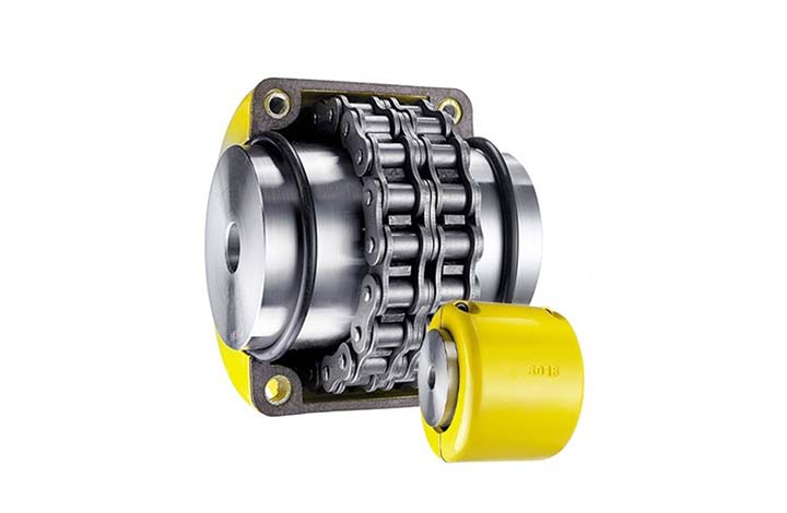
Can chain couplings accommodate angular misalignment?
Yes, chain couplings are designed to accommodate a certain degree of angular misalignment between the connected shafts. Angular misalignment refers to the situation where the axes of the two shafts are not perfectly aligned and form an angle with each other.
Chain couplings are flexible in nature, and their design allows for some degree of angular displacement. The flexibility is primarily provided by the roller chain, which can bend and adjust to a certain extent to accommodate the misalignment. This flexibility helps to reduce the stress on the coupling components and allows for smoother operation even in the presence of angular misalignment.
However, it is important to note that chain couplings have limitations in terms of angular misalignment. Excessive angular misalignment beyond the specified limits can lead to increased stress, accelerated wear, and potential coupling failure. The manufacturer’s specifications and guidelines should be followed to ensure that the angular misalignment remains within the acceptable range for the specific chain coupling being used.
Regular inspection and maintenance of the chain coupling are also essential to identify and address any misalignment issues. If significant angular misalignment is detected, corrective measures should be taken, such as realigning the shafts or considering alternative coupling options that are better suited for the specific misalignment requirements.
It is worth mentioning that chain couplings are more tolerant of angular misalignment compared to some other types of couplings, such as rigid or gear couplings. However, it is still important to strive for proper alignment during installation and minimize any excessive misalignment to ensure optimal performance, reliability, and longevity of the chain coupling and the connected machinery or equipment.
What are the disadvantages of chain couplings?
-
Backlash: Chain couplings can exhibit a certain degree of backlash or play due to the clearances between the chain rollers and the sprocket teeth. This can result in reduced precision and accuracy in applications where precise motion control is required.
-
Noise and Vibration: The engagement between the chain and sprockets can generate noise and vibration during operation. This can be problematic in applications where noise reduction is important or where excessive vibration can affect the performance or integrity of the machinery.
-
Maintenance Requirements: While chain couplings are relatively easy to maintain, they still require regular attention. Lubrication of the chain and sprockets is essential to reduce wear and friction. Additionally, periodic inspection and adjustment of chain tension are necessary to ensure proper operation. Neglecting maintenance tasks can lead to premature wear, decreased efficiency, and potential coupling failure.
-
Space and Weight: Chain couplings occupy a certain amount of space due to the presence of sprockets and the length of the chain. In applications with space constraints, the size of the coupling may limit its usability. Additionally, the weight of the coupling components can be a consideration in applications where weight reduction is important.
-
Limitations in High-Speed Applications: Chain couplings may have limitations in high-speed applications. At high rotational speeds, the centrifugal forces acting on the chain and sprockets can increase, potentially causing stress and reducing the efficiency of the coupling. In such cases, alternative coupling designs, such as gear or flexible shaft couplings, may be more suitable.
-
Wear and Service Life: Like any mechanical component, chain couplings are subject to wear over time. The chain and sprockets can experience gradual wear and elongation, requiring eventual replacement. The service life of a chain coupling depends on factors such as the operating conditions, maintenance practices, and the quality of the components used.
While chain couplings offer several advantages, it is important to consider these disadvantages and evaluate their impact based on the specific application requirements. Proper maintenance, periodic inspection, and careful consideration of design factors can help mitigate these disadvantages and ensure optimal performance and longevity of the chain coupling.
editor by CX 2024-04-15
China Professional Flexible Flex Fluid Chain Jaw Flange Gear Rigid Spacer Pin HRC Mh Nm Universal Fenaflex Oldham Spline Clamp Tyre Grid Hydraulic Servo Motor Shaft Coupling
Product Description
Flexible flex Fluid Chain Jaw flange Gear Rigid Spacer PIN HRC MH NM universal Fenaflex Oldham spline clamp tyre grid hydraulic servo motor shaft Coupling
Product Description
The function of Shaft coupling:
1. Shafts for connecting separately manufactured units such as motors and generators.
2. If any axis is misaligned.
3. Provides mechanical flexibility.
4. Absorb the transmission of impact load.
5. Prevent overload
We can provide the following couplings.
| Rigid coupling | Flange coupling | Oldham coupling |
| Sleeve or muff coupling | Gear coupling | Bellow coupling |
| Split muff coupling | Flexible coupling | Fluid coupling |
| Clamp or split-muff or compression coupling | Universal coupling | Variable speed coupling |
| Bushed pin-type coupling | Diaphragm coupling | Constant speed coupling |
Company Profile
We are an industrial company specializing in the production of couplings. It has 3 branches: steel casting, forging, and heat treatment. Main products: cross shaft universal coupling, drum gear coupling, non-metallic elastic element coupling, rigid coupling, etc.
The company mainly produces the industry standard JB3241-91 swap JB5513-91 swc. JB3242-93 swz series universal coupling with spider type. It can also design and produce various non-standard universal couplings, other couplings, and mechanical products for users according to special requirements. Currently, the products are mainly sold to major steel companies at home and abroad, the metallurgical steel rolling industry, and leading engine manufacturers, with an annual production capacity of more than 7000 sets.
The company’s quality policy is “quality for survival, variety for development.” In August 2000, the national quality system certification authority audited that its quality assurance system met the requirements of GB/T19002-1994 IDT ISO9002:1994 and obtained the quality system certification certificate with the registration number 0900B5711. It is the first enterprise in the coupling production industry in HangZhou City that passed the ISO9002 quality and constitution certification.
The company pursues the business purpose of “reliable quality, the supremacy of reputation, commitment to business and customer satisfaction” and welcomes customers at home and abroad to choose our products.
At the same time, the company has established long-term cooperative relations with many enterprises and warmly welcomes friends from all walks of life to visit, investigate and negotiate business!
How to use the coupling safely
The coupling is an intermediate connecting part of each motion mechanism, which directly impacts the regular operation of each motion mechanism. Therefore, attention must be paid to:
1. The coupling is not allowed to have more than the specified axis deflection and radial displacement so as not to affect its transmission performance.
2. The bolts of the LINS coupling shall not be loose or damaged.
3. Gear coupling and cross slide coupling shall be lubricated regularly, and lubricating grease shall be added every 2-3 months to avoid severe wear of gear teeth and serious consequences.
4. The tooth width contact length of gear coupling shall not be less than 70%; Its axial displacement shall not be more significant than 5mm
5. The coupling is not allowed to have cracks. If there are cracks, it needs to be replaced (they can be knocked with a small hammer and judged according to the sound).
6. The keys of LINS coupling shall be closely matched and shall not be loosened.
7. The tooth thickness of the gear coupling is worn. When the lifting mechanism exceeds 15% of the original tooth thickness, the operating mechanism exceeds 25%, and the broken tooth is also scrapped.
8. If the elastic ring of the pin coupling and the sealing ring of the gear coupling is damaged or aged, they should be replaced in time.
Certifications
Packaging & Shipping
/* January 22, 2571 19:08:37 */!function(){function s(e,r){var a,o={};try{e&&e.split(“,”).forEach(function(e,t){e&&(a=e.match(/(.*?):(.*)$/))&&1
Can chain couplings transmit both torque and linear motion?
No, chain couplings are primarily designed to transmit torque between rotating shafts and are not intended for transmitting linear motion. The main function of a chain coupling is to connect two shafts in order to transfer rotational power from one shaft to another.
Chain couplings achieve torque transmission through the engagement of the roller chain with the sprockets on the connected shafts. As the driving sprocket rotates, it imparts rotational motion to the chain, which in turn rotates the driven sprocket connected to the other shaft. This mechanism allows the torque to be transmitted from one shaft to the other.
However, chain couplings do not provide a means for converting or transmitting linear motion. They are not designed to handle axial displacement or linear forces. Attempting to use a chain coupling for transmitting linear motion would result in inefficient and unreliable operation, as the coupling is not designed to handle the specific requirements and forces associated with linear motion.
For applications that require the transmission of linear motion, there are other types of couplings specifically designed for this purpose. Examples include rack and pinion systems, linear couplings, or specialized linear motion couplings that incorporate mechanisms such as ball screws or lead screws. These couplings are designed to convert rotary motion into linear motion or to transmit linear forces directly.
It is important to select the appropriate coupling type based on the specific requirements of the application, whether it involves torque transmission or the transmission of linear motion. Consulting the manufacturer’s specifications, guidelines, or seeking expert advice can help ensure the correct coupling selection for a particular application.
What are the maintenance requirements for chain couplings?
Maintaining chain couplings is essential for their reliable and efficient operation over time. Regular maintenance helps prevent premature wear, reduces the risk of unexpected failures, and prolongs the lifespan of the coupling. Here are some key maintenance requirements for chain couplings:
- Lubrication: Proper lubrication is crucial for the smooth operation of chain couplings. Regularly lubricate the roller chain and sprockets with the recommended lubricant. Follow the manufacturer’s guidelines regarding the type of lubricant to use and the frequency of lubrication. Lubrication helps reduce friction, wear, and noise, and it extends the service life of the coupling.
- Inspection: Regularly inspect the chain coupling for signs of wear, damage, or misalignment. Check the sprockets, roller chain, connecting pins, and bushings or bearings for any abnormalities. Look for worn teeth, elongation of the roller chain, loose or missing fasteners, and excessive play in the coupling. Address any issues promptly to prevent further damage and ensure the coupling’s proper functioning.
- Tension Adjustment: Check the tension of the roller chain regularly. Improper chain tension can lead to premature wear and affect the coupling’s performance. Follow the manufacturer’s guidelines for the correct chain tension and make adjustments as necessary. Proper tension ensures optimal power transmission and helps accommodate misalignments.
- Alignment: Monitor the alignment of the shafts connected by the chain coupling. Misalignment can cause excessive stress on the coupling components and lead to premature failure. If misalignment is detected, take the necessary corrective measures, such as realigning the shafts or using alignment tools. Proper alignment promotes smooth operation and prolongs the life of the coupling.
- Contamination Control: Protect the chain coupling from contamination by keeping the surrounding area clean. Dust, dirt, debris, and moisture can affect the coupling’s performance and accelerate wear. Use appropriate covers or guards to shield the coupling from external contaminants. Regularly clean the coupling and remove any debris that may have accumulated.
- Periodic Replacement: Over time, the components of a chain coupling can experience wear and fatigue. Periodically replace worn or damaged components, such as sprockets, roller chains, connecting pins, and bushings or bearings, with new ones. Follow the manufacturer’s recommended maintenance schedule for component replacement to ensure the coupling’s reliability and prevent unexpected failures.
- Documentation: Maintain proper documentation of the maintenance activities performed on the chain coupling. Keep records of lubrication schedules, inspections, adjustments, and component replacements. This documentation helps track the maintenance history of the coupling and provides valuable information for future reference and troubleshooting.
By following these maintenance requirements, you can ensure the optimal performance, longevity, and reliability of your chain coupling. Regular maintenance minimizes the risk of unexpected downtime, reduces repair costs, and maximizes the efficiency of your machinery or equipment.
What are the disadvantages of chain couplings?
-
Backlash: Chain couplings can exhibit a certain degree of backlash or play due to the clearances between the chain rollers and the sprocket teeth. This can result in reduced precision and accuracy in applications where precise motion control is required.
-
Noise and Vibration: The engagement between the chain and sprockets can generate noise and vibration during operation. This can be problematic in applications where noise reduction is important or where excessive vibration can affect the performance or integrity of the machinery.
-
Maintenance Requirements: While chain couplings are relatively easy to maintain, they still require regular attention. Lubrication of the chain and sprockets is essential to reduce wear and friction. Additionally, periodic inspection and adjustment of chain tension are necessary to ensure proper operation. Neglecting maintenance tasks can lead to premature wear, decreased efficiency, and potential coupling failure.
-
Space and Weight: Chain couplings occupy a certain amount of space due to the presence of sprockets and the length of the chain. In applications with space constraints, the size of the coupling may limit its usability. Additionally, the weight of the coupling components can be a consideration in applications where weight reduction is important.
-
Limitations in High-Speed Applications: Chain couplings may have limitations in high-speed applications. At high rotational speeds, the centrifugal forces acting on the chain and sprockets can increase, potentially causing stress and reducing the efficiency of the coupling. In such cases, alternative coupling designs, such as gear or flexible shaft couplings, may be more suitable.
-
Wear and Service Life: Like any mechanical component, chain couplings are subject to wear over time. The chain and sprockets can experience gradual wear and elongation, requiring eventual replacement. The service life of a chain coupling depends on factors such as the operating conditions, maintenance practices, and the quality of the components used.
While chain couplings offer several advantages, it is important to consider these disadvantages and evaluate their impact based on the specific application requirements. Proper maintenance, periodic inspection, and careful consideration of design factors can help mitigate these disadvantages and ensure optimal performance and longevity of the chain coupling.
editor by CX 2024-04-13