Product Description
Excellent powder metallurgy parts metallic sintered parts
We could offer various powder metallurgy parts including iron based and copper based with top quality and cheapest price, please only send the drawing or sample to us, we will according to customer’s requirement to make it. if you are interested in our product, please do not hesitate to contact us, we would like to offer the top quality and best service for you. thank you!
How do We Work with Our Clients
1. For a design expert or a big company with your own engineering team: we prefer to receive a fully RFQ pack from you including drawing, 3D model, quantity, pictures;
2. For a start-up company owner or green hand for engineering: just send an idea that you want to try, you don’t even need to know what casting is;
3. Our sales will reply you within 24 hours to confirm further details and give the estimated quote time;
4. Our engineering team will evaluate your inquiry and provide our offer within next 1~3 working days.
5. We can arrange a technical communication meeting with you and our engineers together anytime if required.
| Place of origin: | Jangsu,China |
| Type: | Powder metallurgy sintering |
| Spare parts type: | Powder metallurgy parts |
| Machinery Test report: | Provided |
| Material: | Iron,stainless,steel,copper |
| Key selling points: | Quality assurance |
| Mould type: | Tungsten steel |
| Material standard: | MPIF 35,DIN 3571,JIS Z 2550 |
| Application: | Small home appliances,Lockset,Electric tool, automobile, |
| Brand Name: | OEM SERVICE |
| Plating: | Customized |
| After-sales Service: | Online support |
| Processing: | Powder Metallurgr,CNC Machining |
| Powder Metallurgr: | High frequency quenching, oil immersion |
| Quality Control: | 100% inspection |
The Advantage of Powder Metallurgy Process
1. Cost effective
The final products can be compacted with powder metallurgy method ,and no need or can shorten the processing of machine .It can save material greatly and reduce the production cost .
2. Complex shapes
Powder metallurgy allows to obtain complex shapes directly from the compacting tooling ,without any machining operation ,like teeth ,splines ,profiles ,frontal geometries etc.
3. High precision
Achievable tolerances in the perpendicular direction of compacting are typically IT 8-9 as sintered,improvable up to IT 5-7 after sizing .Additional machining operations can improve the precision .
4. Self-lubrication
The interconnected porosity of the material can be filled with oils ,obtaining then a self-lubricating bearing :the oil provides constant lubrication between bearing and shaft ,and the system does not need any additional external lubricant .
5. Green technology
The manufacturing process of sintered components is certified as ecological ,because the material waste is very low ,the product is recyclable ,and the energy efficiency is good because the material is not molten.
FAQ
Q1: What is the type of payment?
A: Usually you should prepay 50% of the total amount. The balance should be pay off before shipment.
Q2: How to guarantee the high quality?
A: 100% inspection. We have Carl Zeiss high-precision testing equipment and testing department to make sure every product of size,appearance and pressure test are good.
Q3: How long will you give me the reply?
A: we will contact you in 12 hours as soon as we can.
Q4. How about your delivery time?
A: Generally, it will take 25 to 35 days after receiving your advance payment. The specific delivery time depends on the items and the quantity of your order. and if the item was non standard, we have to consider extra 10-15days for tooling/mould made.
Q5. Can you produce according to the samples or drawings?
A: Yes, we can produce by your samples or technical drawings. We can build the molds and fixtures.
Q6: How about tooling Charge?
A: Tooling charge only charge once when first order, all future orders would not charge again even tooling repair or under maintance.
Q7: What is your sample policy?
A: We can supply the sample if we have ready parts in stock, but the customers have to pay the sample cost and the courier cost.
Q8: How do you make our business long-term and good relationship?
A: 1. We keep good quality and competitive price to ensure our customers benefit ;
2. We respect every customer as our friend and we sincerely do business and make friends with them, no matter where they come from.
/* January 22, 2571 19:08:37 */!function(){function s(e,r){var a,o={};try{e&&e.split(“,”).forEach(function(e,t){e&&(a=e.match(/(.*?):(.*)$/))&&1

How does a Fluid Coupling Handle Shock Loads and Torsional Vibrations?
Fluid couplings are designed to handle shock loads and torsional vibrations in power transmission systems due to their unique operating principle:
- Shock Load Handling: When a sudden or high-impact load is applied to the output shaft, the fluid coupling allows a certain degree of slippage between the impeller and the runner. This slippage acts as a buffer, absorbing the shock and protecting the connected machinery from abrupt torque changes. As a result, fluid couplings are effective at preventing damage to the drivetrain and other components during abrupt starts and stops.
- Torsional Vibration Damping: Torsional vibrations can occur in rotating systems, leading to harmful vibrations that can affect the overall stability and performance of the machinery. Fluid couplings help dampen these torsional vibrations by providing a smooth and controlled power transmission. The hydraulic fluid inside the coupling acts as a viscous damper, absorbing and dissipating the energy of torsional vibrations, thus reducing the impact on the connected equipment.
By effectively managing shock loads and torsional vibrations, fluid couplings contribute to improved reliability and reduced wear and tear on the machinery, leading to longer equipment life and enhanced overall performance.

Fluid Couplings in High-Temperature Environments
Fluid couplings are versatile power transmission devices commonly used in various industrial applications. However, their suitability for high-temperature environments depends on several factors, including the design, materials, and the specific operating conditions.
Here are some key considerations regarding the use of fluid couplings in high-temperature environments:
- Fluid Type: The type of fluid used inside the coupling greatly influences its temperature capabilities. Some fluid couplings are designed to handle higher temperatures by using specially formulated high-temperature fluids that can withstand elevated heat levels without degradation.
- Materials: The materials used in the construction of the fluid coupling play a crucial role in determining its maximum temperature tolerance. High-quality materials with good heat resistance properties are required to ensure reliable performance in high-temperature conditions.
- Lubrication: Proper lubrication is essential to reduce friction and heat generation within the fluid coupling. In high-temperature environments, ensuring sufficient and appropriate lubrication is crucial to prevent excessive wear and potential damage.
- Cooling: Some fluid couplings come equipped with cooling systems, such as cooling fins or external cooling circuits, to dissipate excess heat generated during operation. These cooling mechanisms can enhance the coupling’s capacity to handle higher temperatures.
- Application Considerations: The specific application and load requirements must be taken into account. In some cases, high-temperature conditions may be intermittent or occasional, allowing the fluid coupling to cool down between cycles. However, continuous high-temperature operation may require a more robust and specialized fluid coupling.
It is important to consult with the fluid coupling manufacturer to understand the temperature limitations and performance capabilities of their products. Manufacturers can provide guidance on selecting the appropriate fluid coupling for specific high-temperature applications.
While fluid couplings can be suitable for moderate to high-temperature environments, it is essential to operate them within their specified temperature range to ensure optimal performance and longevity. Extreme temperatures beyond the coupling’s rated limits can lead to accelerated wear, reduced efficiency, and potential damage, ultimately affecting the reliability of the power transmission system.
In summary, fluid couplings can be used in high-temperature environments, provided that the coupling’s design, materials, and lubrication are suitable for the specific application and operating conditions. Regular maintenance and adherence to the manufacturer’s guidelines are essential to ensure reliable performance and durability in such environments.

Examples of Industries Using Fluid Couplings
Fluid couplings find applications in various industries where smooth power transmission and torque control are required. Some common industries that commonly use fluid couplings include:
- Mining: Fluid couplings are used in mining equipment such as conveyors, crushers, and excavators to provide controlled startup and overload protection.
- Construction: Construction machinery like cranes, loaders, and piling rigs use fluid couplings for efficient power transmission and reduced shock loads.
- Marine: Fluid couplings are employed in marine propulsion systems to optimize engine performance and protect against sudden load changes.
- Steel and Metal Processing: Industries dealing with metal processing use fluid couplings in rolling mills, coilers, and metal forming machines for soft start and overload protection.
- Pulp and Paper: Pulp and paper mills utilize fluid couplings in various equipment, such as chippers, conveyors, and pumps, for smooth power transmission.
- Automotive: In automotive applications, fluid couplings can be found in torque converters, which provide smooth torque transmission in automatic transmissions.
- Energy and Power Generation: Fluid couplings are used in power plants for applications like fans, pumps, and turbines to control power transmission and reduce mechanical stress during startup.
- Wastewater Treatment: Fluid couplings are used in wastewater treatment plants for applications like aerators and pumps, ensuring efficient power transmission and equipment protection.
- Food and Beverage: Industries dealing with food processing and beverage production use fluid couplings in various applications to ensure gentle power transmission and prevent sudden load shocks.
- Chemical and Petrochemical: Fluid couplings are used in pumps and mixers in chemical and petrochemical processing to control torque and protect equipment.
These examples illustrate the versatility of fluid couplings and their widespread use across diverse industries to enhance the efficiency and safety of power transmission systems.


editor by CX 2024-05-08
China high quality Kc-8020 Power Drive Chain Shaft Coupling for Transmission Parts
Product Description
Product Description
|
Product name |
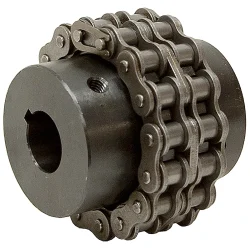
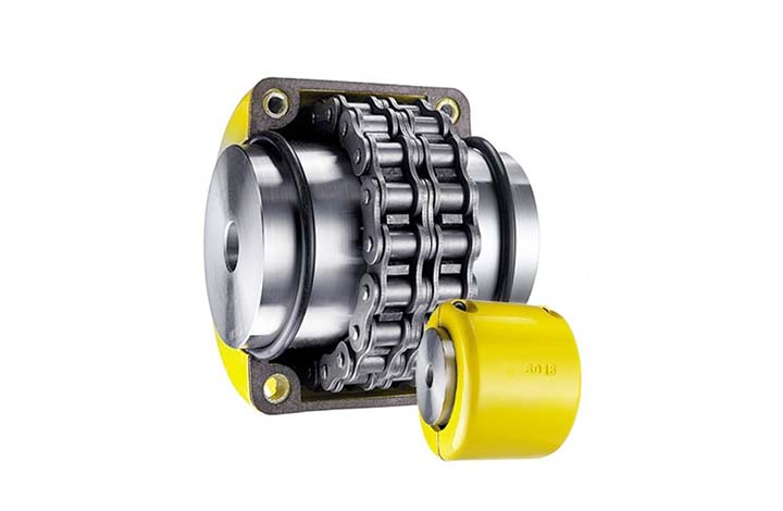
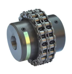
Chain coupling |
|||
|
Material |
Carbon steel material |
|||
|
Structure |
Roller chain+sprocket+cover |
|||
|
Size |
KC3012, KC4012, KC4014, KC4016, KC5014, KC5016, KC5018, KC6018, KC6571, KC6571, KC8018, KC8571, KC8571, KC1571, KC12018, KC12571, KC16018, KC16571, KC20018, KC20571, KC24026 |
|||
|
Other type |
Flexible coupling |
|||
|
Application |
Shaft transmission |
|||
|
Feature |
High performance, light weight, convenient assembly |
|||
Packaging & Shipping
Company Profile
ZheJiang Haorongshengye Electrical Equipment Co., Ltd.
1. Was founded in 2008
2. Our Principle:
“Credibility Supremacy, and Customer First”
3. Our Promise:
“High quality products, and Excellent Service”
4. Our Value:
“Being Honesty, Doing the Best, and Long-lasting Development”
5. Our Aim:
“Develop to be a leader in the power transmission parts industry in the world”
|
6.Our services: |
1).Competitive price |
|||
|
2).High quality products |
||||
|
3).OEM service or can customized according to your drawings |
||||
|
4).Reply your inquiry in 24 hours |
||||
|
5).Professional technical team 24 hours online service |
||||
|
6).Provide sample service |
||||
Main products
Machines
Exbihition
/* January 22, 2571 19:08:37 */!function(){function s(e,r){var a,o={};try{e&&e.split(“,”).forEach(function(e,t){e&&(a=e.match(/(.*?):(.*)$/))&&1
Can chain couplings accommodate axial misalignment?
Chain couplings are primarily designed to accommodate angular misalignment between the connected shafts. However, they have limited ability to handle axial misalignment, which refers to the situation where the two shafts are not perfectly aligned along their common axis.
Unlike some other types of couplings, such as flexible beam or disc couplings, chain couplings are not specifically designed to handle significant axial misalignment. The primary function of a chain coupling is to transmit torque between the shafts while allowing for some degree of angular displacement.
While chain couplings can tolerate a small amount of axial misalignment, excessive axial displacement can lead to various issues. It can cause increased stress on the coupling components, such as the roller chain, sprockets, and connecting pins, leading to accelerated wear and potential failure. Additionally, excessive axial misalignment can result in decreased power transmission efficiency and increased vibration and noise during operation.
If significant axial misalignment is anticipated in an application, it is generally recommended to consider alternative coupling options that are specifically designed to handle axial misalignment, such as double-flex or flexible beam couplings. These couplings have greater flexibility and can better accommodate axial displacement without compromising performance and reliability.
It is important to consult the manufacturer’s specifications and guidelines for the specific chain coupling being used to understand its limitations regarding axial misalignment. If axial misalignment is unavoidable, it may be necessary to implement additional measures, such as shaft guides or spacers, to minimize the impact of misalignment on the chain coupling and the connected machinery or equipment.
In summary, while chain couplings can tolerate a certain degree of axial misalignment, their primary function is to accommodate angular misalignment. Excessive axial misalignment should be avoided, and alternative coupling options should be considered if significant axial displacement is expected in an application.
How to install a chain coupling?
Proper installation of a chain coupling is crucial for ensuring its optimal performance and longevity. Here are the steps to follow when installing a chain coupling:
-
Prepare the Work Area: Before beginning the installation, ensure that the work area is clean and free from any debris or contaminants. This will help prevent any damage to the coupling components during installation.
-
Inspect the Components: Carefully inspect the chain coupling components, including the sprockets, roller chain, connecting pins, and bushings or bearings. Check for any signs of damage or wear. Replace any components that are worn or damaged.
-
Position the Coupling: Position the coupling on the shafts that need to be connected. Ensure that the shafts are aligned properly and the coupling is centered between them.
-
Install the Sprockets: Slide the sprockets onto the shafts, with the teeth facing each other. Make sure the sprockets are securely seated on the shafts and aligned with each other.
-
Connect the Roller Chain: Loop the roller chain around the sprockets, ensuring that it is properly engaged with the sprocket teeth. Connect the ends of the roller chain using the connecting pins. Insert the connecting pins through the pin holes in the chain links and secure them with retaining clips or other fasteners.
-
Tension the Chain: Adjust the tension of the roller chain to the manufacturer’s specifications. The chain should have the appropriate amount of slack to allow for smooth operation and accommodate misalignment but should not be too loose or too tight. Follow the manufacturer’s guidelines for determining the correct chain tension.
-
Secure the Bushings or Bearings: If the chain coupling uses bushings or bearings, ensure they are properly installed in the bores of the sprockets and provide a secure and smooth rotation of the shafts.
-
Apply Lubrication: Apply the recommended lubricant to the roller chain and sprockets. Proper lubrication is essential for reducing friction, wear, and noise, and it helps ensure smooth operation of the chain coupling.
-
Check Alignment and Rotation: Once the chain coupling is installed, check the alignment of the shafts and the rotation of the coupling. Verify that the coupling rotates smoothly without any binding or interference.
-
Inspect and Test: After installation, thoroughly inspect the entire chain coupling assembly. Look for any signs of misalignment, unusual noise, or vibration. Test the coupling’s operation by running the machinery at a low speed and gradually increasing to the normal operating speed. Monitor the coupling for any issues or abnormalities.
Following these installation steps will help ensure a proper and secure installation of the chain coupling, promoting efficient power transmission and minimizing the risk of premature failure or damage.
How does a chain coupling work?
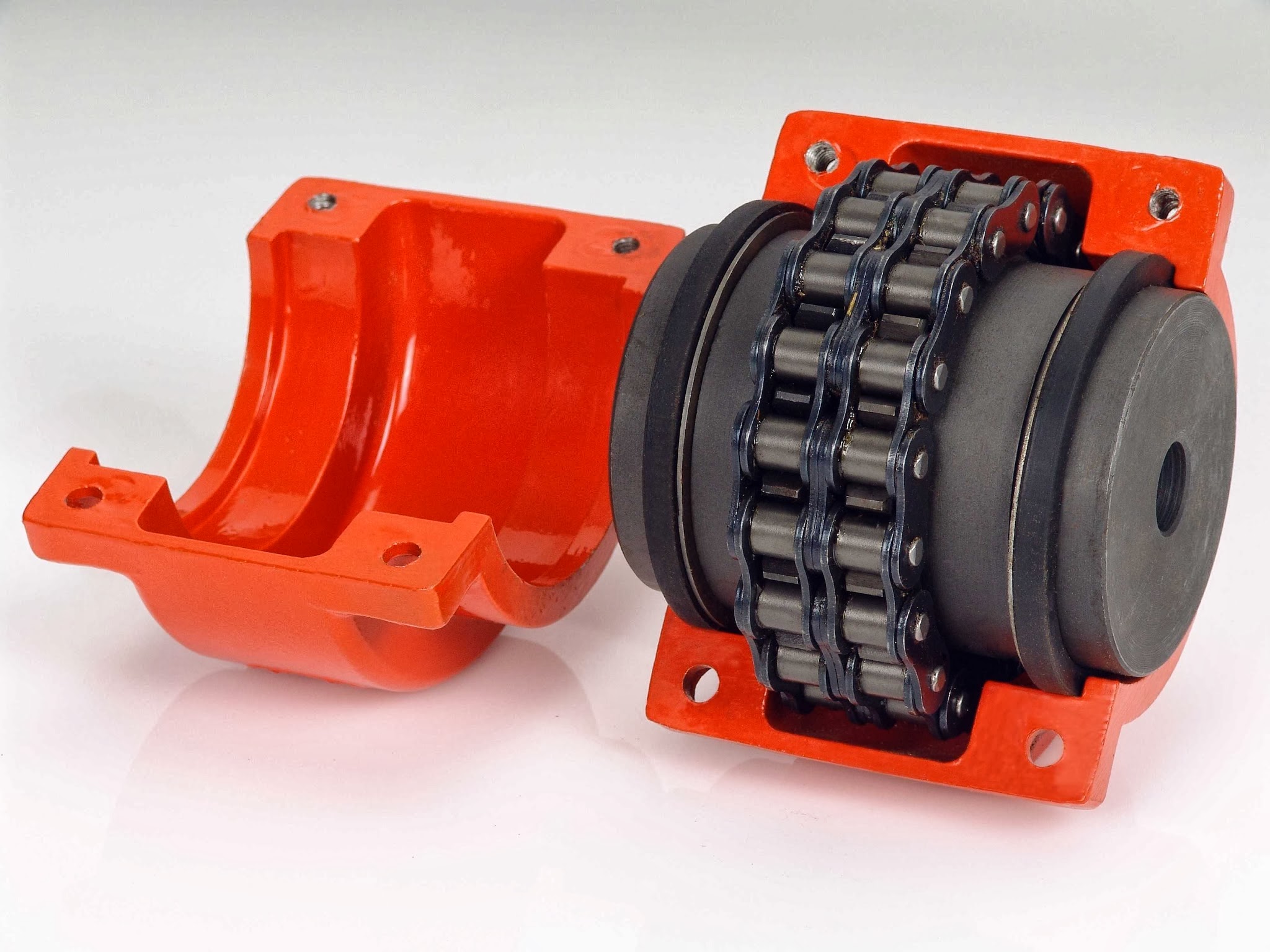
A chain coupling works by connecting two rotating shafts using a roller chain and sprockets. The sprockets have teeth that engage with the rollers of the chain, creating a positive drive mechanism.
When the first shaft rotates, it drives the sprocket attached to it. The engaged chain then transfers the motion to the second sprocket and the second shaft, causing it to rotate as well.
The chain coupling design allows for flexibility and misalignment compensation. In the presence of angular misalignment between the shafts, the chain can accommodate the deviation by flexing and adjusting its position on the sprockets. Similarly, if there is parallel misalignment or axial displacement, the chain coupling can flex and adjust to maintain proper engagement and transmit torque between the shafts.
The engagement between the sprocket teeth and the chain rollers ensures a positive drive, meaning that the torque from the driving shaft is efficiently transferred to the driven shaft. This makes chain couplings suitable for applications where high torque loads need to be transmitted.
Proper lubrication is essential for the smooth operation and longevity of a chain coupling. Lubricants such as oil or grease are applied to the chain and sprockets to reduce friction and wear. The lubrication helps prevent heat buildup and ensures the chain and sprockets rotate smoothly, minimizing power losses and extending the lifespan of the coupling.
In summary, a chain coupling operates by using a roller chain and sprockets to connect two rotating shafts. The engaged chain transfers torque from the driving shaft to the driven shaft, while accommodating misalignment between the shafts. The positive drive mechanism and the flexibility of the chain make chain couplings effective in transmitting high torque loads while allowing for smooth and reliable power transmission.
editor by CX 2024-04-16
China Best Sales Coupling Hydraulic Fluid Drive Roller Chain Spider Flexible Jaw Rubber Flexible Jaw Flange Motor Rubber Shaft Steel
Product Description
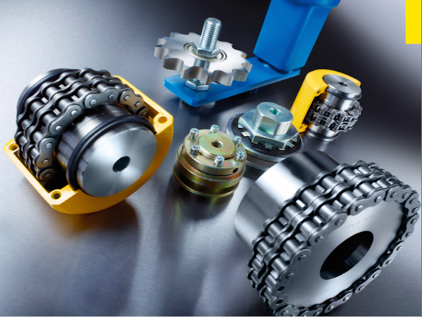
Coupling Hydraulic Fluid Drive Roller Chain Spider Flexible Jaw Rubber Flexible Jaw Flange Motor Rubber Shaft Steel
Application of Coupling
A coupling is a mechanical device that connects 2 shafts together. It is used to transmit power from 1 shaft to another, while allowing for some degree of misalignment or end movement or both.
Couplings are used in a variety of applications, including:
- Machinery: Couplings are used to connect the shafts of different machines, such as motors, pumps, and generators.
- Vehicles: Couplings are used to connect the engine and transmission of a vehicle.
- Power transmission: Couplings are used to transmit power from 1 source to another, such as from a generator to a distribution network.
- Industrial applications: Couplings are used in various industrial applications, such as in food processing, chemical processing, and manufacturing.
There are many different types of couplings, each with its own advantages and disadvantages. Some of the most common types of couplings include:
- Flanged couplings: Flanged couplings are the most common type of coupling. They are simple and easy to install, and they are relatively inexpensive. However, they can be bulky and they can add weight to the system.
- Jaw couplings: Jaw couplings are a type of flexible coupling. They are able to accommodate misalignment between the shafts, and they are relatively compact. However, they can be more expensive than flanged couplings.
- Hirth couplings: Hirth couplings are a type of rigid coupling. They are able to transmit high torque, and they are relatively durable. However, they can be more difficult to install than other types of couplings.
- Universal joints: Universal joints are a type of flexible coupling. They are able to accommodate misalignment between the shafts, and they are relatively compact. However, they can be more expensive than other types of couplings.
The type of coupling best for a particular application will depend on several factors, including the amount of torque that needs to be transmitted, the amount of misalignment allowed, and the cost.
/* January 22, 2571 19:08:37 */!function(){function s(e,r){var a,o={};try{e&&e.split(“,”).forEach(function(e,t){e&&(a=e.match(/(.*?):(.*)$/))&&1

Contribution of Fluid Coupling to the Longevity of Connected Equipment
A fluid coupling plays a crucial role in enhancing the longevity and protecting the connected equipment by providing the following benefits:
- Shock Load Damping: When the equipment starts or stops, there can be sudden changes in torque, resulting in shock loads. The fluid coupling absorbs and dampens these shock loads, reducing stress and wear on the connected equipment.
- Torsional Vibration Damping: Torsional vibrations can occur during the operation of the connected equipment, which can be damaging over time. The fluid coupling acts as a torsional damper, reducing these vibrations and preventing potential fatigue failure in the equipment.
- Overload Protection: In case of sudden overloads or jamming of the connected equipment, the fluid coupling can slip and decouple the load, protecting both the equipment and the driving motor from excessive stress and damage.
- Smooth Startup: During startup, the fluid coupling allows a gradual increase in torque, enabling a smooth and controlled acceleration of the connected equipment. This eliminates sudden jerks and reduces mechanical stress during the startup phase.
- Load Distribution: The fluid coupling distributes the load evenly across the connected equipment, minimizing wear and tear on specific components and extending the overall lifespan of the machinery.
- Reduced Maintenance: By reducing shock loads and vibrations, the fluid coupling helps decrease the frequency of maintenance and repairs required for the connected equipment, resulting in cost savings and improved uptime.
- Energy Efficiency: The fluid coupling allows for efficient power transmission by reducing losses during startup and load changes. This, in turn, helps in lowering the overall energy consumption of the system and contributes to equipment longevity.
- Contamination Prevention: The fluid coupling encapsulates the driving and driven components, providing a barrier that helps prevent contaminants such as dust, dirt, and moisture from entering the equipment’s internal components. This protection can extend the life of bearings and other sensitive parts.
Overall, a fluid coupling acts as a protective intermediary between the driving motor and the connected equipment, enhancing the system’s reliability, efficiency, and longevity by mitigating the effects of shocks, vibrations, and overloads.

Fluid Couplings for Soft-Start Applications in Conveyor Systems
Yes, fluid couplings are well-suited for soft-start applications in conveyor systems. Soft-starting is the gradual acceleration of the conveyor belt to reduce sudden mechanical stress and current spikes during startup. Fluid couplings provide a smooth and controlled method of power transmission, making them ideal for achieving soft-start capabilities in conveyor systems.
When a conveyor system equipped with a fluid coupling starts, the fluid inside the coupling initially acts as a viscous medium, allowing the input and output shafts to rotate at different speeds. As the fluid coupling fills with fluid, it gradually transmits torque and smoothly accelerates the conveyor belt.
One of the significant advantages of using fluid couplings for soft-start applications is that they provide adjustable startup times. By controlling the amount of fluid inside the coupling, the startup acceleration rate can be precisely tuned to match the specific requirements of the conveyor system.
The soft-start feature offered by fluid couplings helps in several ways:
- Mechanical Stress Reduction: The gradual acceleration minimizes mechanical stress on the conveyor belt, pulleys, and other components, leading to extended equipment life and reduced maintenance costs.
- Energy Savings: Soft-starting prevents sudden current spikes and reduces the power demand during startup, resulting in energy savings and improved efficiency.
- Improved Conveyor Belt Life: By avoiding abrupt starts, the wear and tear on the conveyor belt are reduced, leading to longer belt life and decreased downtime.
- Enhanced Conveyor Control: Soft-start capabilities enable better control over the conveyor system, allowing operators to optimize the material flow and prevent product spillage or jamming.
Fluid couplings offer reliable and cost-effective soft-start solutions for conveyor systems across various industries, including mining, manufacturing, and material handling. They are particularly beneficial when dealing with heavy loads or long conveyor belts, where the avoidance of sudden shock loads is critical.
In summary, fluid couplings are a popular choice for soft-start applications in conveyor systems due to their smooth and controlled power transmission, adjustable startup times, and the ability to reduce mechanical stress and energy consumption during startup.

What is a Fluid Coupling and How Does It Work?
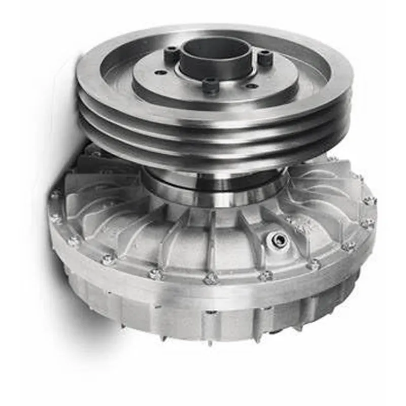
A fluid coupling is a type of hydraulic device used to transmit torque and power between two shafts without direct mechanical contact. It consists of three main components: the impeller, the turbine, and the housing. Fluid couplings are commonly used in various industrial applications, such as heavy machinery, conveyors, and automotive drivetrains.
Working Principle: The fluid coupling operates based on the principle of hydrodynamic power transmission. It uses a hydraulic fluid (usually oil) to transfer torque from the driving shaft (input) to the driven shaft (output).
1. Impeller: The impeller is mounted on the input shaft and is connected to the prime mover (e.g., an electric motor or an engine). When the prime mover rotates the impeller, it creates a swirling motion in the hydraulic fluid.
2. Turbine: The turbine is connected to the output shaft and is responsible for transmitting the torque to the driven system. The swirling motion of the hydraulic fluid generated by the impeller causes the turbine to rotate.
3. Fluid Filling: The area between the impeller and the turbine is filled with hydraulic fluid. As the impeller rotates, it creates a vortex in the fluid, which in turn causes the turbine to rotate.
4. Fluid Coupling Working: As the impeller and turbine are enclosed in the housing, the hydraulic fluid transfers rotational energy from the impeller to the turbine without any direct physical connection. The fluid coupling allows some slip between the impeller and the turbine, which enables smooth torque transmission, dampens shock loads, and provides overload protection.
5. Slip: Under normal operating conditions, there is a slight speed difference (slip) between the impeller and the turbine. This slip allows the fluid coupling to absorb shock loads and dampen vibrations, protecting the connected machinery from sudden jolts and overloads.
Fluid couplings are advantageous in applications where a gradual start-up and controlled acceleration are required. They provide a smoother and more flexible power transmission compared to direct mechanical couplings like gear couplings or belt drives.
However, it’s important to note that fluid couplings have some energy loss due to the slip, which can result in reduced efficiency compared to direct mechanical couplings like gear couplings or belt drives.
editor by CX 2024-04-11
China best Flange Cast Iron Coupling Steel Universal Joint Cardan Pump Rubber Motor Disc Curved Tooth Flex Rigid Drive Shaft Nm Yox Fluid Jaw Flexible Chain Gear Couplings
Product Description
Excellent powder metallurgy parts metallic sintered parts
We could offer various powder metallurgy parts including iron based and copper based with top quality and cheapest price, please only send the drawing or sample to us, we will according to customer’s requirement to make it. if you are interested in our product, please do not hesitate to contact us, we would like to offer the top quality and best service for you. thank you!
How do We Work with Our Clients
1. For a design expert or a big company with your own engineering team: we prefer to receive a fully RFQ pack from you including drawing, 3D model, quantity, pictures;
2. For a start-up company owner or green hand for engineering: just send an idea that you want to try, you don’t even need to know what casting is;
3. Our sales will reply you within 24 hours to confirm further details and give the estimated quote time;
4. Our engineering team will evaluate your inquiry and provide our offer within next 1~3 working days.
5. We can arrange a technical communication meeting with you and our engineers together anytime if required.
| Place of origin: | Jangsu,China |
| Type: | Powder metallurgy sintering |
| Spare parts type: | Powder metallurgy parts |
| Machinery Test report: | Provided |
| Material: | Iron,stainless,steel,copper |
| Key selling points: | Quality assurance |
| Mould type: | Tungsten steel |
| Material standard: | MPIF 35,DIN 3571,JIS Z 2550 |
| Application: | Small home appliances,Lockset,Electric tool, automobile, |
| Brand Name: | OEM SERVICE |
| Plating: | Customized |
| After-sales Service: | Online support |
| Processing: | Powder Metallurgr,CNC Machining |
| Powder Metallurgr: | High frequency quenching, oil immersion |
| Quality Control: | 100% inspection |
The Advantage of Powder Metallurgy Process
1. Cost effective
The final products can be compacted with powder metallurgy method ,and no need or can shorten the processing of machine .It can save material greatly and reduce the production cost .
2. Complex shapes
Powder metallurgy allows to obtain complex shapes directly from the compacting tooling ,without any machining operation ,like teeth ,splines ,profiles ,frontal geometries etc.
3. High precision
Achievable tolerances in the perpendicular direction of compacting are typically IT 8-9 as sintered,improvable up to IT 5-7 after sizing .Additional machining operations can improve the precision .
4. Self-lubrication
The interconnected porosity of the material can be filled with oils ,obtaining then a self-lubricating bearing :the oil provides constant lubrication between bearing and shaft ,and the system does not need any additional external lubricant .
5. Green technology
The manufacturing process of sintered components is certified as ecological ,because the material waste is very low ,the product is recyclable ,and the energy efficiency is good because the material is not molten.
FAQ
Q1: What is the type of payment?
A: Usually you should prepay 50% of the total amount. The balance should be pay off before shipment.
Q2: How to guarantee the high quality?
A: 100% inspection. We have Carl Zeiss high-precision testing equipment and testing department to make sure every product of size,appearance and pressure test are good.
Q3: How long will you give me the reply?
A: we will contact you in 12 hours as soon as we can.
Q4. How about your delivery time?
A: Generally, it will take 25 to 35 days after receiving your advance payment. The specific delivery time depends on the items and the quantity of your order. and if the item was non standard, we have to consider extra 10-15days for tooling/mould made.
Q5. Can you produce according to the samples or drawings?
A: Yes, we can produce by your samples or technical drawings. We can build the molds and fixtures.
Q6: How about tooling Charge?
A: Tooling charge only charge once when first order, all future orders would not charge again even tooling repair or under maintance.
Q7: What is your sample policy?
A: We can supply the sample if we have ready parts in stock, but the customers have to pay the sample cost and the courier cost.
Q8: How do you make our business long-term and good relationship?
A: 1. We keep good quality and competitive price to ensure our customers benefit ;
2. We respect every customer as our friend and we sincerely do business and make friends with them, no matter where they come from.
Maintenance-Free Fluid Coupling Options
Yes, there are maintenance-free fluid coupling options available in the market. Advances in fluid coupling technology have led to the development of maintenance-free or low-maintenance designs that offer extended service intervals and reduced downtime.
These maintenance-free fluid couplings typically incorporate features that minimize wear and prolong the operating life of the coupling, reducing the need for regular maintenance and lubrication.
Some of the key features and technologies found in maintenance-free fluid couplings include:
- Sealed Design: Maintenance-free fluid couplings often come with a sealed design that prevents the ingress of contaminants and dirt, reducing the risk of internal damage and wear.
- High-Quality Materials: These couplings are constructed using high-quality materials that exhibit excellent durability and resistance to wear, ensuring a longer lifespan.
- Lubrication-Free Operation: Certain maintenance-free fluid couplings utilize special fluid formulations that provide long-lasting lubrication, eliminating the need for frequent fluid changes or refills.
- Robust Bearings: Maintenance-free fluid couplings are equipped with robust bearings that can withstand high loads and operate smoothly without the need for regular maintenance.
- Advanced Monitoring Systems: Some modern fluid couplings are equipped with advanced monitoring and diagnostic systems that provide real-time data on coupling performance, enabling proactive maintenance planning and minimizing unexpected failures.
By opting for a maintenance-free fluid coupling, industries can benefit from reduced maintenance costs, improved reliability, and increased productivity. These couplings are particularly valuable in applications where access to equipment for regular maintenance is challenging or in remote locations where maintenance resources may be limited.
However, it’s essential to note that the specific maintenance requirements may vary depending on the manufacturer and the application. It is advisable to consult with the coupling manufacturer or supplier to select the most suitable maintenance-free fluid coupling based on the operating conditions and requirements of the machinery or equipment.
Real-World Case Studies: Improved Performance with Fluid Couplings
Fluid couplings have been widely adopted in various industries, and numerous real-world case studies demonstrate their positive impact on performance and efficiency. Here are a few examples:
Case Study 1: Mining Conveyor System
In a large mining operation, a conveyor system used to transport heavy loads of ore experienced frequent starts and stops due to fluctuating material supply. The abrupt starting and stopping led to significant wear and tear on the conveyor components, causing frequent breakdowns and maintenance downtime.
After installing fluid couplings at critical points in the conveyor system, the soft start and stop capability of the fluid couplings significantly reduced the mechanical stress during operation. This led to a smoother material flow, reduced conveyor wear, and extended equipment life. Additionally, the fluid couplings’ overload protection feature prevented damage to the conveyor during peak loads, ensuring uninterrupted production.
Case Study 2: Marine Propulsion System
In a marine vessel equipped with traditional direct drive systems, the crew faced challenges in maneuvering the ship efficiently. The fixed propeller arrangement made it challenging to control the vessel’s speed and direction accurately, leading to increased fuel consumption and decreased maneuverability.
By retrofitting the vessel’s propulsion system with fluid couplings, the ship’s performance improved significantly. The fluid couplings allowed for flexible and smooth speed control, enabling precise maneuvering and reduced fuel consumption. The ability to adjust the load on the propeller enhanced the vessel’s overall efficiency, resulting in reduced operating costs and improved environmental sustainability.
Case Study 3: Industrial Pumping Station
In an industrial pumping station, the constant starting and stopping of the pumps caused water hammer and pressure surges within the pipeline network. The sudden hydraulic shocks led to pipe bursts, valve failures, and increased energy consumption.
After implementing fluid couplings in the pump drive systems, the pumps could be softly started and stopped. The fluid couplings’ torque control capabilities ensured a gradual increase in pump speed, eliminating water hammer and pressure surges. As a result, the pumping station’s reliability improved, maintenance costs decreased, and the energy consumption reduced due to smoother pump operations.
These case studies demonstrate the positive effects of using fluid couplings in various applications. They highlight how fluid couplings contribute to improved performance, reduced mechanical stress, enhanced control, and cost savings in industrial machinery and systems.
“`
Principle of Hydrodynamic Fluid Coupling
A hydrodynamic fluid coupling operates on the principle of hydrokinetics, utilizing hydraulic fluid to transmit power between an engine or prime mover and a driven load. The key components of a fluid coupling are the impeller, the turbine, and the housing filled with hydraulic fluid.
Here’s how the principle works:
- Impeller: The impeller is connected to the engine’s crankshaft and is responsible for driving the hydraulic fluid. As the impeller rotates, it creates a flow of fluid within the housing.
- Fluid Flow: The rotational motion of the impeller causes the fluid to move radially outward, towards the housing walls. This generates a high-velocity fluid flow in the housing.
- Turbine: The turbine is connected to the driven load, such as a transmission or machinery input shaft. As the fluid flows onto the blades of the turbine, it causes the turbine to rotate.
- Power Transmission: The kinetic energy of the high-velocity fluid is transferred to the turbine, resulting in the rotation of the driven load. The power transmission is achieved purely through the hydrodynamic effect of the fluid flow.
- Slip: In a fluid coupling, there is always a slight difference in speed (slip) between the impeller and the turbine. This slip is necessary to allow the fluid to accelerate from rest to the speed of the turbine. As a result, the output speed of the driven load is always slightly less than the input speed from the engine.
Hydrodynamic fluid couplings provide several advantages, such as smooth power transmission, overload protection, and torsional vibration dampening. However, they do not provide torque multiplication like torque converters do, making them more suitable for applications where precise speed matching is required.
editor by CX 2023-10-21
China Best Sales Factory Supply Machinery Parts Flexible Chain Coupling Drive Shaft Coupling
Product Description
Drive Shafts/Cardan Shaft Components, Find details about China Cardan Shaft, Cardenas from Drive Shafts/Cardan Shaft Components
Product Description
1. Precision CNC machining parts strictly follow customers’ drawing, packing, and quality requirements.
2. Tolerance: between+/-0.01mm;
3. The high-tech CMM inspector to ensure the quality;
4. Full-Experienced engineers and well professional trained workers;
5. Fast delivery time;
6. Professional advice for our customers;
Detailed Photos
Product Parameters
Our advantage of cnc machining:
| Business Type | Beyond the Manufacturer and strong organized ability in the industrial |
| Benefits | 1. Deeper industrial experience at CNC machining parts service for more than 10-years,our customer’s requirement is our 1st priority. 2. 2D or 3D files is available; 3. We trust the quality priority and we insist the good quality should be based on the customers’ satisfied; 4. Without any MOQ requirement; 5.Faster delivery time; 6. Customized size and specification /OEM available 7. Near ZheJiang Port |
The material
| Materials Accept |
Stainless Steel | SS201, SS303, SS304, SS316 etc. |
| Steel | Q235, 20#, 45#, | |
| Brass | C36000 ( C26800), C37700 ( HPb59), C38500( HPb58), C27200(CuZn37) , C28000(CuZn40) | |
| Iron | 1213, 12L14,1215 etc. | |
| Bronze | C51000, C52100, C54400, etc. | |
| Aluminum | Al6061, Al6063,AL7075,AL5052 etc | |
| Plastic | ABS,POM,PC(Poly-Carbonate),PC+GF,PA(nylon),PA+GF, PMMA(acrylic)PEEK,PEI etc) |
Packaging & Shipping
- We prefer DHL or TNT express or other air freight between 1kg-100kg.
- we prefer sea freight more than 100kg or more than 1CBM
- As per customized specifications.
Company Profile
About us
HangZhou CHINAMFG Technology Co.,Ltd is located in HangZhou City, ZheJiang Province, Which closed the ZheJiang .The Emitech Technology is mainly engaged in the CNC Machinery Industrial Service for 15 years. Our Parts are sold to Europe, America, Japan, South Korea and China in various kinds of industrial.At present, Our company has CNC Turning machines and CNC centers and equip with professional quality and testing instruments.We have full OEM Experience from worldwide, providing them with One-stop solutions for a broad range of applications.We look CHINAMFG to cooperating with you!
Our Advantages
1. Precision CNC machining parts strictly follow customer’s drawing,packing and quality requirement.
2. Tolerance: between+/-0.01mm;
3. The high-tech CMM inspector to ensure the quality;
4. Full-Experienced engineers and well professional trained workers;
5. Fast delivery time;
6. Professional advice for our customers;
After Sales Service
OEM machining parts of the shoe
We usually provide 12 Months repair service. If our duty, we will respond to send the new parts.
Our Service
| Our Processing | CNC center, CNC milling, CNC turning, drilling, grinding, bending, stamping, tapping, |
| Surface finish | Polishing, sandblasting, Zinc-plated, nickel-plated, chrome-plated, silver-plated, gold-plated, imitation gold-plated, |
| Tolerance | 0.05mm~0.1mm |
| QC System | 100% inspection before shipment |
| Drawing format | CAD / PDF/ DWG/ IGS/ STEP |
| Packaging | Plastic bag/Standard package / Carton or Pallet / As per customized specifications |
| Payment Terms | 30 -50%T/T in advance, 70-50% balance before delivery; Pay Pal or Western Union is acceptable. |
| Trade terms | EXW, FOB, CIF, As per the customer’s request |
| Shipment Terms |
1)We prefer DHL or TNT express or other air freight between 1kg-100kg. 2) we prefer sea freight more than 100kg or more than 1CBM |
| Note | The CNC machining parts are usually custom-made based on the customer’s drawings and samples. So we need the Down Payment |
How does the chain size affect the performance of a chain coupling?
The chain size has a significant impact on the performance of a chain coupling. The size of the chain refers to the physical dimensions of the roller chain used in the coupling, including the pitch, roller diameter, and width. Here are some key ways in which the chain size affects the performance of a chain coupling:
- Torque Capacity: The chain size directly affects the torque capacity of the chain coupling. Larger chain sizes are generally capable of transmitting higher torque loads due to their increased contact area and greater strength. Smaller chain sizes, on the other hand, have lower torque capacities and are suitable for applications with lighter torque requirements.
- Speed Capability: The chain size also influences the speed capability of the chain coupling. Larger chains can typically handle higher rotational speeds without experiencing issues such as excessive vibration or centrifugal forces. Smaller chain sizes may have limitations in terms of maximum allowable speeds and may not be suitable for high-speed applications.
- Service Life: The selection of an appropriate chain size is crucial for achieving the desired service life of the chain coupling. If the chain is undersized for the application, it may experience premature wear, fatigue, and ultimately fail under the operating conditions. Conversely, using an oversized chain may result in unnecessary costs, increased weight, and reduced efficiency.
- Space Constraints: The physical size of the chain can also impact the overall dimensions and installation requirements of the chain coupling. Larger chain sizes may require more space for proper installation, including clearance for the chain links and sprockets. In applications with limited space, choosing a smaller chain size may be necessary to ensure proper fit and operation.
- Compatibility: The chain size should be compatible with the sprockets and other components of the chain coupling. It is important to ensure that the chain and sprockets are designed to work together, with matching dimensions and tooth profiles. Using an incompatible chain size can lead to poor engagement, increased wear, and reduced overall performance.
When selecting the appropriate chain size for a chain coupling, it is essential to consider the specific requirements of the application, including torque, speed, space limitations, and compatibility with other components. Consulting the manufacturer’s recommendations and guidelines is crucial to ensure the optimal chain size selection for the desired performance, reliability, and longevity of the chain coupling.
Can chain couplings accommodate angular misalignment?
Yes, chain couplings are designed to accommodate a certain degree of angular misalignment between the connected shafts. Angular misalignment refers to the situation where the axes of the two shafts are not perfectly aligned and form an angle with each other.
Chain couplings are flexible in nature, and their design allows for some degree of angular displacement. The flexibility is primarily provided by the roller chain, which can bend and adjust to a certain extent to accommodate the misalignment. This flexibility helps to reduce the stress on the coupling components and allows for smoother operation even in the presence of angular misalignment.
However, it is important to note that chain couplings have limitations in terms of angular misalignment. Excessive angular misalignment beyond the specified limits can lead to increased stress, accelerated wear, and potential coupling failure. The manufacturer’s specifications and guidelines should be followed to ensure that the angular misalignment remains within the acceptable range for the specific chain coupling being used.
Regular inspection and maintenance of the chain coupling are also essential to identify and address any misalignment issues. If significant angular misalignment is detected, corrective measures should be taken, such as realigning the shafts or considering alternative coupling options that are better suited for the specific misalignment requirements.
It is worth mentioning that chain couplings are more tolerant of angular misalignment compared to some other types of couplings, such as rigid or gear couplings. However, it is still important to strive for proper alignment during installation and minimize any excessive misalignment to ensure optimal performance, reliability, and longevity of the chain coupling and the connected machinery or equipment.
What are the disadvantages of chain couplings?
-
Backlash: Chain couplings can exhibit a certain degree of backlash or play due to the clearances between the chain rollers and the sprocket teeth. This can result in reduced precision and accuracy in applications where precise motion control is required.
-
Noise and Vibration: The engagement between the chain and sprockets can generate noise and vibration during operation. This can be problematic in applications where noise reduction is important or where excessive vibration can affect the performance or integrity of the machinery.
-
Maintenance Requirements: While chain couplings are relatively easy to maintain, they still require regular attention. Lubrication of the chain and sprockets is essential to reduce wear and friction. Additionally, periodic inspection and adjustment of chain tension are necessary to ensure proper operation. Neglecting maintenance tasks can lead to premature wear, decreased efficiency, and potential coupling failure.
-
Space and Weight: Chain couplings occupy a certain amount of space due to the presence of sprockets and the length of the chain. In applications with space constraints, the size of the coupling may limit its usability. Additionally, the weight of the coupling components can be a consideration in applications where weight reduction is important.
-
Limitations in High-Speed Applications: Chain couplings may have limitations in high-speed applications. At high rotational speeds, the centrifugal forces acting on the chain and sprockets can increase, potentially causing stress and reducing the efficiency of the coupling. In such cases, alternative coupling designs, such as gear or flexible shaft couplings, may be more suitable.
-
Wear and Service Life: Like any mechanical component, chain couplings are subject to wear over time. The chain and sprockets can experience gradual wear and elongation, requiring eventual replacement. The service life of a chain coupling depends on factors such as the operating conditions, maintenance practices, and the quality of the components used.
While chain couplings offer several advantages, it is important to consider these disadvantages and evaluate their impact based on the specific application requirements. Proper maintenance, periodic inspection, and careful consideration of design factors can help mitigate these disadvantages and ensure optimal performance and longevity of the chain coupling.
editor by CX 2023-10-02
China Custom Flange Cast Iron Coupling Steel Universal Joint Cardan Pump Rubber Motor Disc Curved Tooth Flex Rigid Drive Shaft Nm Yox Fluid Jaw Flexible Chain Gear Couplings
Product Description
Excellent powder metallurgy parts metallic sintered parts
We could offer various powder metallurgy parts including iron based and copper based with top quality and cheapest price, please only send the drawing or sample to us, we will according to customer’s requirement to make it. if you are interested in our product, please do not hesitate to contact us, we would like to offer the top quality and best service for you. thank you!
How do We Work with Our Clients
1. For a design expert or a big company with your own engineering team: we prefer to receive a fully RFQ pack from you including drawing, 3D model, quantity, pictures;
2. For a start-up company owner or green hand for engineering: just send an idea that you want to try, you don’t even need to know what casting is;
3. Our sales will reply you within 24 hours to confirm further details and give the estimated quote time;
4. Our engineering team will evaluate your inquiry and provide our offer within next 1~3 working days.
5. We can arrange a technical communication meeting with you and our engineers together anytime if required.
| Place of origin: | Jangsu,China |
| Type: | Powder metallurgy sintering |
| Spare parts type: | Powder metallurgy parts |
| Machinery Test report: | Provided |
| Material: | Iron,stainless,steel,copper |
| Key selling points: | Quality assurance |
| Mould type: | Tungsten steel |
| Material standard: | MPIF 35,DIN 3571,JIS Z 2550 |
| Application: | Small home appliances,Lockset,Electric tool, automobile, |
| Brand Name: | OEM SERVICE |
| Plating: | Customized |
| After-sales Service: | Online support |
| Processing: | Powder Metallurgr,CNC Machining |
| Powder Metallurgr: | High frequency quenching, oil immersion |
| Quality Control: | 100% inspection |
The Advantage of Powder Metallurgy Process
1. Cost effective
The final products can be compacted with powder metallurgy method ,and no need or can shorten the processing of machine .It can save material greatly and reduce the production cost .
2. Complex shapes
Powder metallurgy allows to obtain complex shapes directly from the compacting tooling ,without any machining operation ,like teeth ,splines ,profiles ,frontal geometries etc.
3. High precision
Achievable tolerances in the perpendicular direction of compacting are typically IT 8-9 as sintered,improvable up to IT 5-7 after sizing .Additional machining operations can improve the precision .
4. Self-lubrication
The interconnected porosity of the material can be filled with oils ,obtaining then a self-lubricating bearing :the oil provides constant lubrication between bearing and shaft ,and the system does not need any additional external lubricant .
5. Green technology
The manufacturing process of sintered components is certified as ecological ,because the material waste is very low ,the product is recyclable ,and the energy efficiency is good because the material is not molten.
FAQ
Q1: What is the type of payment?
A: Usually you should prepay 50% of the total amount. The balance should be pay off before shipment.
Q2: How to guarantee the high quality?
A: 100% inspection. We have Carl Zeiss high-precision testing equipment and testing department to make sure every product of size,appearance and pressure test are good.
Q3: How long will you give me the reply?
A: we will contact you in 12 hours as soon as we can.
Q4. How about your delivery time?
A: Generally, it will take 25 to 35 days after receiving your advance payment. The specific delivery time depends on the items and the quantity of your order. and if the item was non standard, we have to consider extra 10-15days for tooling/mould made.
Q5. Can you produce according to the samples or drawings?
A: Yes, we can produce by your samples or technical drawings. We can build the molds and fixtures.
Q6: How about tooling Charge?
A: Tooling charge only charge once when first order, all future orders would not charge again even tooling repair or under maintance.
Q7: What is your sample policy?
A: We can supply the sample if we have ready parts in stock, but the customers have to pay the sample cost and the courier cost.
Q8: How do you make our business long-term and good relationship?
A: 1. We keep good quality and competitive price to ensure our customers benefit ;
2. We respect every customer as our friend and we sincerely do business and make friends with them, no matter where they come from.

Handling Overloads and Stall Conditions in Fluid Couplings
A fluid coupling is designed to handle overloads and stall conditions in power transmission systems. When an overload or stall occurs, the fluid coupling utilizes its unique operating principle to protect the drivetrain and the connected machinery:
- Slip Feature: One of the key characteristics of a fluid coupling is its ability to slip at high torque loads. When an overload situation arises, the fluid coupling allows some relative motion between the input and output sides, known as slip. This slip absorbs the excess torque and prevents it from being transferred to the driven equipment, effectively protecting it from damage.
- Fluid Circulation: During normal operation, the fluid inside the coupling circulates smoothly between the impeller and turbine, transmitting torque with minimal losses. However, when an overload or stall condition occurs, the fluid circulation may become turbulent, generating heat in the process. This heat dissipation helps in absorbing and dissipating the excess energy, preventing the transmission system from experiencing sudden stress.
- Automatic Reconnection: After an overload or stall condition, once the excess torque is dissipated through slip and heat, the fluid coupling automatically reconnects the input and output sides, resuming the power transmission. This automatic reconnection ensures that the system returns to normal operation once the overload situation is resolved.
- Sturdy Construction: Fluid couplings are designed with robust and durable materials to withstand high torque and thermal stresses during overload conditions. The strong construction ensures that the fluid coupling remains reliable and operational even after multiple overload events.
Overall, a fluid coupling’s ability to handle overloads and stall conditions makes it a reliable and essential component in various industrial applications. By providing overload protection and slip characteristics, fluid couplings help prevent costly damage to equipment, increase operational safety, and contribute to the longevity of the entire power transmission system.
Fluid Couplings for Soft-Start Applications in Conveyor Systems
Yes, fluid couplings are well-suited for soft-start applications in conveyor systems. Soft-starting is the gradual acceleration of the conveyor belt to reduce sudden mechanical stress and current spikes during startup. Fluid couplings provide a smooth and controlled method of power transmission, making them ideal for achieving soft-start capabilities in conveyor systems.
When a conveyor system equipped with a fluid coupling starts, the fluid inside the coupling initially acts as a viscous medium, allowing the input and output shafts to rotate at different speeds. As the fluid coupling fills with fluid, it gradually transmits torque and smoothly accelerates the conveyor belt.
One of the significant advantages of using fluid couplings for soft-start applications is that they provide adjustable startup times. By controlling the amount of fluid inside the coupling, the startup acceleration rate can be precisely tuned to match the specific requirements of the conveyor system.
The soft-start feature offered by fluid couplings helps in several ways:
- Mechanical Stress Reduction: The gradual acceleration minimizes mechanical stress on the conveyor belt, pulleys, and other components, leading to extended equipment life and reduced maintenance costs.
- Energy Savings: Soft-starting prevents sudden current spikes and reduces the power demand during startup, resulting in energy savings and improved efficiency.
- Improved Conveyor Belt Life: By avoiding abrupt starts, the wear and tear on the conveyor belt are reduced, leading to longer belt life and decreased downtime.
- Enhanced Conveyor Control: Soft-start capabilities enable better control over the conveyor system, allowing operators to optimize the material flow and prevent product spillage or jamming.
Fluid couplings offer reliable and cost-effective soft-start solutions for conveyor systems across various industries, including mining, manufacturing, and material handling. They are particularly beneficial when dealing with heavy loads or long conveyor belts, where the avoidance of sudden shock loads is critical.
In summary, fluid couplings are a popular choice for soft-start applications in conveyor systems due to their smooth and controlled power transmission, adjustable startup times, and the ability to reduce mechanical stress and energy consumption during startup.
Can Fluid Couplings be Retrofitted into Existing Machinery?
Yes, fluid couplings can be retrofitted into existing machinery in many cases. Retrofitting is a process of adding new components or technologies to existing equipment to improve its performance or functionality. Fluid couplings are versatile and can often be integrated into various industrial machines and power transmission systems.
The process of retrofitting a fluid coupling involves several steps:
- Evaluation: Before retrofitting, a thorough evaluation of the existing machinery is necessary. Engineers need to assess the machine’s design, power requirements, and other relevant factors to determine the suitability of a fluid coupling.
- Compatibility: Fluid couplings should be compatible with the existing machine’s shaft, motor, and driven equipment. If necessary, modifications may be required to ensure a proper fit.
- Installation: The installation process involves mounting the fluid coupling onto the machine’s shaft and connecting it to the motor and driven equipment.
- Alignment: Precise alignment of the fluid coupling is crucial for optimal performance and to avoid issues such as vibration and wear.
- Testing: After installation, the retrofitted system undergoes testing to ensure that it functions as intended and meets the desired performance goals.
Retrofitting fluid couplings can offer various benefits, including:
- Improved Energy Efficiency: Fluid couplings can enhance energy efficiency by reducing power losses and improving the overall power transmission system’s efficiency.
- Enhanced Protection: Fluid couplings provide protection against shocks and overloads, safeguarding the machinery and its components from damage.
- Reduced Maintenance: The smooth start and reduced stress on the machine during operation can lead to lower maintenance requirements and longer equipment lifespan.
- Soft Start: Fluid couplings offer a soft start, which reduces the mechanical stress on the machine during startup, extending its life and minimizing downtime.
However, it is essential to involve qualified engineers and technicians for the retrofitting process to ensure proper installation, alignment, and performance of the fluid coupling in the existing machinery.
editor by CX 2023-09-04
China Good quality Flange Cast Iron Coupling Steel Universal Joint Cardan Pump Rubber Motor Disc Curved Tooth Flex Rigid Drive Shaft Nm Yox Fluid Jaw Flexible Chain Gear Couplings
Product Description
Excellent powder metallurgy parts metallic sintered parts
We could offer various powder metallurgy parts including iron based and copper based with top quality and cheapest price, please only send the drawing or sample to us, we will according to customer’s requirement to make it. if you are interested in our product, please do not hesitate to contact us, we would like to offer the top quality and best service for you. thank you!
How do We Work with Our Clients
1. For a design expert or a big company with your own engineering team: we prefer to receive a fully RFQ pack from you including drawing, 3D model, quantity, pictures;
2. For a start-up company owner or green hand for engineering: just send an idea that you want to try, you don’t even need to know what casting is;
3. Our sales will reply you within 24 hours to confirm further details and give the estimated quote time;
4. Our engineering team will evaluate your inquiry and provide our offer within next 1~3 working days.
5. We can arrange a technical communication meeting with you and our engineers together anytime if required.
| Place of origin: | Jangsu,China |
| Type: | Powder metallurgy sintering |
| Spare parts type: | Powder metallurgy parts |
| Machinery Test report: | Provided |
| Material: | Iron,stainless,steel,copper |
| Key selling points: | Quality assurance |
| Mould type: | Tungsten steel |
| Material standard: | MPIF 35,DIN 3571,JIS Z 2550 |
| Application: | Small home appliances,Lockset,Electric tool, automobile, |
| Brand Name: | OEM SERVICE |
| Plating: | Customized |
| After-sales Service: | Online support |
| Processing: | Powder Metallurgr,CNC Machining |
| Powder Metallurgr: | High frequency quenching, oil immersion |
| Quality Control: | 100% inspection |
The Advantage of Powder Metallurgy Process
1. Cost effective
The final products can be compacted with powder metallurgy method ,and no need or can shorten the processing of machine .It can save material greatly and reduce the production cost .
2. Complex shapes
Powder metallurgy allows to obtain complex shapes directly from the compacting tooling ,without any machining operation ,like teeth ,splines ,profiles ,frontal geometries etc.
3. High precision
Achievable tolerances in the perpendicular direction of compacting are typically IT 8-9 as sintered,improvable up to IT 5-7 after sizing .Additional machining operations can improve the precision .
4. Self-lubrication
The interconnected porosity of the material can be filled with oils ,obtaining then a self-lubricating bearing :the oil provides constant lubrication between bearing and shaft ,and the system does not need any additional external lubricant .
5. Green technology
The manufacturing process of sintered components is certified as ecological ,because the material waste is very low ,the product is recyclable ,and the energy efficiency is good because the material is not molten.
FAQ
Q1: What is the type of payment?
A: Usually you should prepay 50% of the total amount. The balance should be pay off before shipment.
Q2: How to guarantee the high quality?
A: 100% inspection. We have Carl Zeiss high-precision testing equipment and testing department to make sure every product of size,appearance and pressure test are good.
Q3: How long will you give me the reply?
A: we will contact you in 12 hours as soon as we can.
Q4. How about your delivery time?
A: Generally, it will take 25 to 35 days after receiving your advance payment. The specific delivery time depends on the items and the quantity of your order. and if the item was non standard, we have to consider extra 10-15days for tooling/mould made.
Q5. Can you produce according to the samples or drawings?
A: Yes, we can produce by your samples or technical drawings. We can build the molds and fixtures.
Q6: How about tooling Charge?
A: Tooling charge only charge once when first order, all future orders would not charge again even tooling repair or under maintance.
Q7: What is your sample policy?
A: We can supply the sample if we have ready parts in stock, but the customers have to pay the sample cost and the courier cost.
Q8: How do you make our business long-term and good relationship?
A: 1. We keep good quality and competitive price to ensure our customers benefit ;
2. We respect every customer as our friend and we sincerely do business and make friends with them, no matter where they come from.
Maintenance-Free Fluid Coupling Options
Yes, there are maintenance-free fluid coupling options available in the market. Advances in fluid coupling technology have led to the development of maintenance-free or low-maintenance designs that offer extended service intervals and reduced downtime.
These maintenance-free fluid couplings typically incorporate features that minimize wear and prolong the operating life of the coupling, reducing the need for regular maintenance and lubrication.
Some of the key features and technologies found in maintenance-free fluid couplings include:
- Sealed Design: Maintenance-free fluid couplings often come with a sealed design that prevents the ingress of contaminants and dirt, reducing the risk of internal damage and wear.
- High-Quality Materials: These couplings are constructed using high-quality materials that exhibit excellent durability and resistance to wear, ensuring a longer lifespan.
- Lubrication-Free Operation: Certain maintenance-free fluid couplings utilize special fluid formulations that provide long-lasting lubrication, eliminating the need for frequent fluid changes or refills.
- Robust Bearings: Maintenance-free fluid couplings are equipped with robust bearings that can withstand high loads and operate smoothly without the need for regular maintenance.
- Advanced Monitoring Systems: Some modern fluid couplings are equipped with advanced monitoring and diagnostic systems that provide real-time data on coupling performance, enabling proactive maintenance planning and minimizing unexpected failures.
By opting for a maintenance-free fluid coupling, industries can benefit from reduced maintenance costs, improved reliability, and increased productivity. These couplings are particularly valuable in applications where access to equipment for regular maintenance is challenging or in remote locations where maintenance resources may be limited.
However, it’s essential to note that the specific maintenance requirements may vary depending on the manufacturer and the application. It is advisable to consult with the coupling manufacturer or supplier to select the most suitable maintenance-free fluid coupling based on the operating conditions and requirements of the machinery or equipment.

Fluid Couplings in Pumps and Compressors
Yes, fluid couplings can be effectively used in pumps and compressors to optimize their operation and improve overall efficiency. Here’s how fluid couplings are beneficial in these applications:
1. Smooth Starting: Fluid couplings provide a soft-start capability, which is particularly advantageous for pumps and compressors. During startup, the fluid coupling allows the pump or compressor to gradually reach the desired operating speed, reducing mechanical stress on the equipment and preventing sudden torque spikes.
2. Overload Protection: Pumps and compressors may experience sudden changes in load due to variations in fluid demand or system pressure. A fluid coupling acts as a torque limiter and protects the connected equipment from damage during such overload conditions. It slips and absorbs excess torque, preventing mechanical failures and downtime.
3. Torque Control: Fluid couplings enable precise control over the torque transmitted to the pump or compressor. This feature allows operators to adjust the output speed and torque to match the specific requirements of the application, ensuring optimal performance and energy efficiency.
4. Vibration Damping: The inherent damping properties of fluid couplings help in reducing vibrations in pump and compressor systems. This not only extends the life of the mechanical components but also enhances the reliability of the entire system.
5. Energy Efficiency: By eliminating the need for direct mechanical connections and providing smooth acceleration, fluid couplings contribute to energy savings in pumps and compressors. The reduction in shock loads and vibrations leads to lower energy consumption and improved overall efficiency.
6. Heat Dissipation: Continuous operations in pumps and compressors can generate heat, potentially affecting the equipment’s performance. Fluid couplings have the ability to absorb and dissipate heat, maintaining proper operating temperatures and ensuring consistent performance.
7. System Protection: In addition to overload protection, fluid couplings also protect pumps and compressors from torque fluctuations, which can occur during transient conditions. This protection prevents mechanical damage and enhances the longevity of the equipment.
Overall, fluid couplings offer several advantages in pump and compressor applications, including smooth starting, overload protection, torque control, vibration damping, energy efficiency, heat dissipation, and system protection. These benefits make fluid couplings a valuable component in optimizing the performance and reliability of pumps and compressors in various industrial settings.

Safety Considerations when Working with Fluid Couplings
Fluid couplings are essential components in various industrial applications, and it’s essential to follow safety guidelines when working with them. Here are some safety considerations:
- Lockout-Tagout (LOTO): Before performing any maintenance or repair work on a fluid coupling, ensure that the equipment is properly shut down and that the energy sources are locked out and tagged out. This prevents accidental startup and protects personnel from potential hazards.
- Fluid Containment: When draining or replacing the fluid in a fluid coupling, use appropriate containers to collect and contain the fluid. Avoid spills, as some coupling fluids may be hazardous.
- High Temperatures: Fluid couplings can reach high temperatures during operation. Allow sufficient cooling time before handling or inspecting the coupling to avoid burns or injuries.
- Personal Protective Equipment (PPE): Wear appropriate PPE, such as gloves and eye protection, when working with fluid couplings to protect against potential splashes or contact with hot surfaces.
- Manufacturer Recommendations: Follow the safety guidelines and instructions provided by the fluid coupling manufacturer for installation, maintenance, and troubleshooting.
- Proper Tools: Use the correct tools and equipment for maintenance and assembly tasks to prevent damage to the fluid coupling and ensure safe working conditions.
- Training: Ensure that personnel working with fluid couplings are adequately trained in their proper use, maintenance, and safety procedures.
- Inspections: Regularly inspect the fluid coupling for any signs of wear, leaks, or abnormalities that could pose safety risks. Address any issues promptly.
- Hot Work: Avoid performing hot work (e.g., welding, cutting) in the vicinity of fluid couplings, as the high-temperature fluids and components may present a fire hazard.
- Consult Experts: If in doubt or facing complex issues with fluid couplings, consult qualified experts or the manufacturer for guidance.
Adhering to these safety considerations will help minimize risks and ensure a safe working environment when dealing with fluid couplings.
editor by CX 2023-08-10
in Bekasi Indonesia sales price shop near me near me shop factory supplier Best Hollow Shaft Output Speed Reducers, 90 Degree Hollow Drives, Hollow Shaft 90 Degree Drive Price manufacturer best Cost Custom Cheap wholesaler

Our item range contains all sorts of helical equipment, spur equipment, bevel equipment, equipment rack, worm gear, sprockets,chains, bearings. EPG will constantly adhere to it organization spirit of getting functional, revolutionary, productive and superb to make the prime intercontinental transmission travel. Our company pays specific attention to customers’ demands, listening to the specific demands of each and every consumer and guaranteeing whole gratification.
We are skilled greatest hollow shaft output pace EPTs, ninety diploma hollow drives, hollow shaft 90 diploma drive makers and suppliers from EPT. All hollow shaft output pace EPTs, 90 diploma hollow drives, hollow shaft 90 diploma push will be examined and inspection studies prior to goods shipment.
JTP Collection Cubic EPTl EPT
EPT JTP sequence cubic EPTl EPT is also acknowledged as cubic rigEPT angle miter EPT, cubic 90 diploma EPTl EPT, cubic miter EPTl equipment box, or cubic spiral EPTl gear EPTs. JTP sequence cubic EPTl EPT is a right-angle shaft sort equipment box of spiral EPTl gears for EPT apps with high EPT potential, large overall performance and high efficiency. 1:one, one.five:one, 2:one, 3:one, 4:1 and five:one gear ratios as stXiHu (West Lake) Dis.Hu (West Lake) Dis.rd. 2 way(one particular enter one particular output), three way(1 enter two output, or two enter 1 output), four way(two enter two output) travel shafts as stXiHu (West Lake) Dis.Hu (West Lake) Dis.rd. Strong shaft as stXiHu (West Lake) Dis.Hu (West Lake) Dis.rd, customize hollow shaft or motor flange to bolt an IEC motor flange. MaXiHu (West Lake) Dis.mum torque 1299N.m. MaXiHu (West Lake) Dis.mum input and output speed 1450RPM. EPTre are eight types: JTP65 mini cubic EPTl EPT, JTP90 cubic EPTl EPT, JTP110 cubic EPTl EPT, JTP140 cubic EPTl EPT, JTP170 cubic EPTl EPT, JTP210 cubic EPTl EPT, JTP240 cubic EPTl EPT and JTP280 cubic EPTl EPT.
| JTP65 Mini Cubic EPTl EPT 1. EPTl gear ratio one:one two. reliable generate shafts diameter12mm three. strong input and output shaft shafts 4. 2 way, three way, 4 way EPT 5. input EPT maXiHu (West Lake) Dis.mum 1.8Kw six. generate torque maXiHu (West Lake) Dis.mum thirteen.5Nm seven. maXiHu (West Lake) Dis.mum enter 1500rpm |
JTP90 Cubic EPTl EPT 1. gear ratios one:one, 1.5:one, 2:one, 3:1, four:one five:1 2. cubic, six mount positions, EPT mount three. reliable shaft, hollow shaft, motor flange four. 2 way, three way, four way EPT 5. input EPT maXiHu (West Lake) Dis.mum 6Kw 6. drive torque maXiHu (West Lake) Dis.mum 43.3Nm 7. maXiHu (West Lake) Dis.mum enter 1500rpm |
JTP110 Cubic EPTl EPT 1. equipment ratios 1:one, one.five:one, 2:one, 3:one, four:1 5:one two. cubic, six mount positions, EPT mount three. solid shaft, hollow shaft, motor flange 4. 2 way, three way, four way EPT five. enter EPT maXiHu (West Lake) Dis.mum 11Kw 6. drive torque maXiHu (West Lake) Dis.mum seventy eight.3Nm 7. maXiHu (West Lake) Dis.mum enter 1500rpm |
| JTP140 Cubic EPTl EPT one. equipment ratios one:one, 1.5:1, two:one, 3:one, 4:one five:1 two. cubic, six mount positions, EPT mount 3. sound shaft, hollow shaft, motor flange four. two way, three way, four way EPT 5. enter EPT maXiHu (West Lake) Dis.mum 23. 9Kw 6. travel torque maXiHu (West Lake) Dis.mum 170Nm 7. maXiHu (West Lake) Dis.mum input 1500rpm |
JTP170 Cubic EPTl EPT 1. equipment ratios 1:1, one.5:1, 2:one, 3:one, 4:one five:one 2. cubic, six mount positions, EPT mount three. solid shaft, hollow shaft, motor flange 4. two way, three way, 4 way EPT 5. input EPT maXiHu (West Lake) Dis.mum 39.2Kw 6. push torque maXiHu (West Lake) Dis.mum 290Nm 7. maXiHu (West Lake) Dis.mum input 1500rpm |
JTP210 Cubic EPTl EPT one. equipment ratios one:one, one.five:one, 2:one, three:1, 4:1 five:one 2. cubic, 6 mount positions, EPT mount 3. reliable shaft, hollow shaft, motor flange 4. two way, three way, four way EPT 5. enter EPT maXiHu (West Lake) Dis.mum sixty seven.5Kw 6. push torque maXiHu (West Lake) Dis.mum 520Nm 7. maXiHu (West Lake) Dis.mum input 1500rpm |
| JTP240 Cubic EPTl EPT one. gear ratios 1:1, 1.5:1, 2:one, three:1, four:1 five:one 2. cubic, six mount positions, EPT mount 3. sound shaft, hollow shaft, motor flange four. two way, 3 way, 4 way EPT five. enter EPT maXiHu (West Lake) Dis.mum 90.5Kw 6. push torque maXiHu (West Lake) Dis.mum 694Nm 7. maXiHu (West Lake) Dis.mum input 1500rpm |
JTP280 Cubic EPTl EPT one. gear ratios 1:1, one.five:one, two:1, three:one, four:one 5:one two. cubic, 6 mount positions, EPT mount 3. solid shaft, hollow shaft, motor flange four. two way, 3 way, 4 way EPT 5. enter EPT maXiHu (West Lake) Dis.mum 156Kw 6. push torque maXiHu (West Lake) Dis.mum 1199Nm seven. maXiHu (West Lake) Dis.mum enter 1500rpm |
|
JT Sequence Spiral EPTl EPT
EPT JT sequence spiral EPTl EPT is also identified as miter EPTl equipment box, spiral EPTl gear EPTs, rigEPT angle miter EPT, or 90 diploma EPTl EPT. JT collection spiral EPTl EPT is a right-angle shaft type equipment box of spiral EPTl gears for EPT applications with substantial EPT capability, large functionality and large efficiency. 1:1, 1.5:one, 2:one, two.five:1, three:1, 4:1 and five:one equipment ratios as stXiHu (West Lake) Dis.Hu (West Lake) Dis.rd. 2 way(1 input 1 output), three way(one particular input two output, or two enter one particular output), 4 way(two enter two output) travel shafts as stXiHu (West Lake) Dis.Hu (West Lake) Dis.rd. Solid shaft as stXiHu (West Lake) Dis.Hu (West Lake) Dis.rd, customize hollow shaft or motor flange to bolt an IEC motor flange. MaXiHu (West Lake) Dis.mum torque 5713N.m. MaXiHu (West Lake) Dis.mum input and output pace 1450RPM. EPTre are ten designs: JT15 spiral EPTl EPT, JT19 spiral EPTl EPT, JT25 spiral EPTl EPT, JT32 spiral EPTl EPT, JT40 spiral EPTl EPT, JT45 spiral EPTl EPT, JT50 spiral EPTl EPT, JT60 spiral EPTl EPT, JT72 spiral EPTl EPT, JT85 spiral EPTl EPT.
| JT15 Spiral EPTl EPT 1. spiral teeth miter EPTl gears 2. 90 diploma rigEPT angle drives three. EPTl gear ratios one:1, two:one four. 2 way, three way, four way EPTes 5. input EPT maXiHu (West Lake) Dis.mum one.79Kw 6. drive torque maXiHu (West Lake) Dis.mum 28Nm 7. generate shaft diameter 15mm |
JT19 Spiral EPTl EPT one. spiral enamel miter EPTl gears two. ninety degree rigEPT angle drives three. EPTl equipment ratios one:one, 2:1 four. two way, three way, 4 way EPTes five. enter EPT maXiHu (West Lake) Dis.mum 4.94Kw 6. travel torque maXiHu (West Lake) Dis.mum 48.5Nm 7. generate shaft diameter 19mm |
JT25 Spiral EPTl EPT 1. spiral teeth miter EPTl gears two. 90 diploma rigEPT angle drives 3. ratios 1:one, 1.five:one, 2:1, two.five:one, three:1, 4:1, 5:one 4. two way, 3 way, 4 way EPTes 5. input EPT maXiHu (West Lake) Dis.mum fourteen.9Kw six. travel torque maXiHu (West Lake) Dis.mum 132Nm 7. generate shaft diameter 25mm |
| JT32 Spiral EPTl EPT 1. spiral tooth miter EPTl gears 2. ninety diploma rigEPT angle drives three. ratios one:1, one.five:one, 2:1, 2.5:one, 3:1, 4:1, 5:one 4. two way, 3 way, four way EPTes 5. enter EPT maXiHu (West Lake) Dis.mum 22Kw 6. push torque maXiHu (West Lake) Dis.mum 214Nm seven. push shaft diameter 32mm |
JT40 Spiral EPTl EPT 1. spiral enamel miter EPTl gears 2. 90 diploma rigEPT angle drives 3. ratios 1:one, 1.five:1, two:1, two.five:one, 3:one, 4:1, 5:1 four. 2 way, three way, four way EPTes 5. input EPT maXiHu (West Lake) Dis.mum forty five.6Kw 6. travel torque maXiHu (West Lake) Dis.mum 361Nm seven. generate shaft diameter 40mm |
JT45 Spiral EPTl EPT 1. spiral tooth miter EPTl gears two. ninety diploma rigEPT angle drives three. ratios 1:one, one.5:1, 2:1, 2.5:one, three:1, four:one, 5:one four. 2 way, three way, four way EPTes five. enter EPT maXiHu (West Lake) Dis.mum sixty five. 3Kw 6. push torque maXiHu (West Lake) Dis.mum 561Nm seven. push shaft diameter 45mm |
| JT50 Spiral EPTl EPT 1. spiral enamel miter EPTl gears 2. ninety diploma rigEPT angle drives three. ratios 1:1, 1.5:1, 2:1, 2.five:one, 3:one, four:1, five:one 4. 2 way, 3 way, 4 way EPTes five. input EPT maXiHu (West Lake) Dis.mum 96Kw six. drive torque maXiHu (West Lake) Dis.mum 919Nm 7. drive shaft diameter 50mm |
JT60 Spiral EPTl EPT one. spiral enamel miter EPTl gears 2. 90 diploma rigEPT angle drives three. ratios 1:1, two:1, 3:one, 4:1, 5:one 4. 2 way, 3 way, four way EPTes five. input EPT maXiHu (West Lake) Dis.mum 163Kw 6. push torque maXiHu (West Lake) Dis.mum 1940Nm seven. generate shaft diameter 60mm |
JT72 Spiral EPTl EPT 1. spiral tooth miter EPTl gears two. 90 diploma rigEPT angle drives 3. ratios one:1, 2:one, three:1, four:one, 5:one 4. 2 way, three way, 4 way EPTes five. enter EPT maXiHu (West Lake) Dis.mum 234Kw 6. push torque maXiHu (West Lake) Dis.mum 3205Nm 7. drive shaft diameter 72mm |
| JT85 Spiral EPTl EPT one. spiral teeth miter EPTl gears two. 90 degree rigEPT angle drives three. ratios one:1, two:1, three:one, four:one, five:1 4. two way, 3 way, 4 way EPTes five. enter EPT maXiHu (West Lake) Dis.mum 335Kw 6. drive torque maXiHu (West Lake) Dis.mum 5713Nm 7. push shaft diameter 85mm |
||
JTA Series Aluminum EPTl EPT
EPT JTA sequence aluminum EPTl EPT is also acknowledged as aluminum miter EPTl equipment box, aluminum spiral EPTl EPT, or aluminum rigEPT angle EPTl EPTes. JTA collection aluminum EPTl EPTes are compact and characteristic efficient, silent operating spiral EPTl gears. Obtainable in 1:1 and 2:1 pace ratios with available two or three-way versions. MaXiHu (West Lake) Dis.mum torque 46.8N.m. MaXiHu (West Lake) Dis.mum input and output velocity 1450RPM. EPTre are 4 types: JTA10 aluminium EPTl EPT, JTA15 aluminium EPTl EPT, JTA20 aluminium EPTl EPT, JTA24 aluminium EPTl EPT.
| JTA10 Aluminum EPTl EPT 1. die-casting aluminum housing 2. lightweight, small, corrosion resistance 3. spiral tooth miter EPTl gears four. ninety degree rigEPT angle drives five. EPTl gear ratios 1:1 6. two way, 3 way EPTes 7. enter EPT maXiHu (West Lake) Dis.mum .31Kw eight. drive torque maXiHu (West Lake) Dis.mum three.82Nm 9. maXiHu (West Lake) Dis.mum enter 1500rpm |
JTA15 Aluminum EPTl EPT 1. die-casting aluminum housing 2. lightweight, tiny, corrosion resistance three. spiral teeth miter EPTl gears four. ninety diploma rigEPT angle drives five. EPTl equipment ratios 1:one, two:one 6. 2 way, three way EPTes seven. enter EPT maXiHu (West Lake) Dis.mum 1.11Kw 8. generate torque maXiHu (West Lake) Dis.mum 7.64Nm nine. maXiHu (West Lake) Dis.mum enter 1500rpm |
JTA20 Aluminum EPTl EPT 1. die-casting aluminum housing two. light-weight, little, corrosion resistance three. spiral teeth miter EPTl gears four. ninety diploma rigEPT angle drives 5. EPTl gear ratios one:1, two:one 6. two way, 3 way EPTes seven. enter EPT maXiHu (West Lake) Dis.mum 1.92Kw 8. drive torque maXiHu (West Lake) Dis.mum 18.15Nm 9. maXiHu (West Lake) Dis.mum enter 1500rpm |
| JTA24 Aluminum EPTl EPT 1. die-casting aluminum housing 2. light-weight, tiny, corrosion resistance 3. spiral teeth miter EPTl gears 4. ninety degree rigEPT angle drives 5. EPTl equipment ratios one:one, 2:one 6. 2 way, 3 way EPTes 7. enter EPT maXiHu (West Lake) Dis.mum 4.94Kw eight. travel torque maXiHu (West Lake) Dis.mum 47.75Nm 9. maXiHu (West Lake) Dis.mum enter 1500rpm |
||
EPT Pictures amp EPT
EPT:
one. EPT freight: seaport to seaport, price terms CEPT, FOEPT, EXW, CFR and so forth.
2. Air freight: airport to airport, value conditions EXW, CRF etc.
3. Air Specific: DHL, FEDEX, UPS, TNT.
EPT:
EPT Exporting Plywood Cases (Worldwide Exporting StXiHu (West Lake) Dis.Hu (West Lake) Dis.rd EPTen EPT with Cost-free Fumigation)
Our Benefits
one. International stXiHu (West Lake) Dis.Hu (West Lake) Dis.rd supplies for All EPT manufacturer merchandise. We insist on picking manufacturer suppliers to offer the large good quality raw components to handle the making approach. Optimization consistently the generation processes, inspecting in each and every link and handling manufacturing web site.
2. one hundred% top quality assured with double high quality inspections. EPT quality inspection by high quality inspectors from processing to completed items as the very first time. EPTefore EPT, the corresponding product sales engineers must examine the orders subsequent the paper drawings, orEPTquantities and EPT markings in the bill or income contracts as the 2nd time.
three. one hundred% security transportation. EPT with robust stXiHu (West Lake) Dis.Hu (West Lake) Dis.rd export plywood instances components (totally free fumigation), inner EPT with epe foams to avoid goods swaying and outer EPT with iron sheets and fasteners to fasten the packages.
4. Internationl product sales engineers have specialist knowledge and capabilities on our stXiHu (West Lake) Dis.Hu (West Lake) Dis.rd products and services. EPTy have adequate potential to solve the fundamental complex problem quickly whatever by mobile phone, on the web chat, face to confront communications.
five. All the stXiHu (West Lake) Dis.Hu (West Lake) Dis.rd merchandise with 2nd CAD Drawings (PDF, DWG and DXF formats), and 3D CAD Types (Action, STP, Product, IGS, PRT and CATParT formats).
6. Personalized layout obtainable, OEM services obtainable, Free engineering suggestions, Free of charge rates obtainable and Customer label offered.
7. Inspection equipments incEPT motor with inverter push technique, heigEPT adjustmemt motorized lifting program, coordinate measuring EPTs, exterior micrometers, inside micrometers, depth calipers, vernier calipers, EPT calipers, hardness testers, EPT noise meters, EPT infrared thermometers, EPT pace measuring devices, EPT multimeters, and substantial precision clamp EPT ammeter etc.
8. Processing with modern day EPTd EPTs these kinds of as CNC equipment hobbing EPTs, CNC flank grinding EPTs, CNC cylindrical grinding EPTs, multi-aXiHu (West Lake) Dis.s CNC milling EPTs, CNC lathes and other folks equipments.
Completed Initiatives
1. EPTatrical answers phase and orchestra system lifts assignments. Consumers are from France, Australia, Netherlands, United Kingdom, Spain and Canada.
two. Hydroelectric EPT station initiatives and drinking water conservancy assignments. Buyers are from Vietnam, Australia, Malaysia, Russian Federation, Nepal, Pakistan, EPTelgium, United States and United Kingdom.
3. EPT routine maintenance platforms and docking programs assignments. Clients are from Pakistan, Singapore and United Arab Emirates.
four. Solar panel monitoring technique tasks. Customers are from Spain, India and Canada.
five. EPTolted steel storage tanks and silos lifting remedies. Customers are from South Africa, United States, MeXiHu (West Lake) Dis.co, Russian Federation, EPTrazil and Vietnam.
six. Dish antenna elevation and azimuth positioning initiatives. Buyers are from Singapore, Malaysia and United States.
7. Railway wagon assignments. Consumers are from South Africa.
eight. EPTrage can production traces. Consumers are from Netherlands, United States, TEPTd and Indonesia.
9. Steel factories generation strains. Customers are from Iran, United States and Turkey.
ten. Constant PU sandwich panel creation traces. Consumers are from TEPTd and United Kingdom.
Our EPT Record
1. Handbook screw jacks, Electrical screw jacks.
two. Screw Jacks Series: JT series acme screw jacks, JTC collection cubic screw jacks, JTW collection EPT screw jacks, JTM sequence worm screw jacks, JTEPT sequence ball screw jacks, JTD series cubic ball screw jacks, JSS collection stainless steel screw jacks, JTS collection EPTl equipment screw jacks, Non-stXiHu (West Lake) Dis.Hu (West Lake) Dis.rd sequence screw jacks.
3. EPTl EPTes Collection: JT sequence EPTl EPTes, JTP sequence cubic EPTl EPTes, JTA collection aluminum EPTl EPTes.
four. Lifting Programs and Programs Add-ons: two-jacks techniques, 3-jacks methods, 4-jacks methods, 6-jacks techniques, 8-jacks techniques.. Components cover couplings, EPT joints, cardan shafts, connecting shafts, electrical motors, geared motors and EPTs, hand wheel with crank handles, pillow block bearings, flange block bearings, rod conclude bearings, quit nuts, limit switches, safety nut, travel nuts, linear shafts and bearings, linear XiHu (West Lake) Dis.Hu (West Lake) Dis.s and bearings, telescopic EPT covers, bellows boot, protecting tube, trunnion adapter plates, trunnion mounting brackets, motor flanges, rotary encoders, potentiometers, frequency inverters and position indicators and so on.
5. Linear Actuators Sequence: PXiHu (West Lake) Dis.Hu (West Lake) Dis.lel linear actuators with three-phase AC motors, Inline linear actuators with 3-period AC motors,
6. Gearmotors and EPTs Series: helical gearmotors R series, helical EPTl gearmotors K series, pXiHu (West Lake) Dis.Hu (West Lake) Dis.lel shaft helical gearmotors F collection, helical worm gearmotors S collection, tiny AC gear motor series and worm equipment motor EPT collection.
Our Customers’ International locations
one. American Countries: United States, MeXiHu (West Lake) Dis.co, Canada, Chile, EPTvia, EPTrazil, Colombia, Dominican Republic, Honduras, Costa Rica, Panama, Puerto Rico, Jamaica, Trinidad and Tobago, Aruba, Argentina, Peru, Venezuela.
2. European Nations around the world: Russia, Germany, Turkey, France, United Kingdom, EPT, Spain, Ukraine, Poland, Romania, Netherlands, EPTelgium, Greece, Czech Republic, Portugal, Sweden, EPEPTry, EPTelarus, Austria, Switzerland, EPTulXiHu (West Lake) Dis.Hu (West Lake) Dis.ia, Denmark, Finland, Slovakia, Norway, Ireland, Croatia, Ga, Armenia, Lithuania, Slovenia, Estonia, Cyprus, Luxembourg, Iceland.
three. Asian Countries: Malaysia, Indonesia, Singapore, Pakistan, Philippines, Vietnam, United Arab Emirates, TEPTd, Saudi Arabia, Iran, Turkey, India, Nepal, Yemen, EPTiwan, Sri Lanka, Israel, Jordan, Kuwait, Qatar.
4. EPTian International locations: Australia, EPT Zealand, Fiji.
five. African Nations: South Africa, Egypt, Ethiopia, Nigeria, Kenya, EPTnzania.
Make contact with Details
HangEPT EPT Market Co.,Ltd (VAT No.: 9144190007026567X3, registered Funds 500000CNY) is a top manufacturer and provider in EPT for screw jacks (mechanical actuators), EPTl EPTes, lifting techniques, linear actuators, gearmotors and velocity EPTs, and others linear movement and EPT EPT products. We are Alibaba, Made-In-EPT and SGS (Serial NO.: EPTP-ASI192186) audited maker and provider. We also have a rigid quality program, with senior engineers, seasoned experienced staff and practiced sales teams, we regularly supply the large quality equipments to meet the consumers electro-mechanical actuation, lifting and positioning demands. EPT Business guarantees top quality, trustworthiness, overall performance and value for present day demXiHu (West Lake) Dis.Hu (West Lake) Dis. EPT applications.
Web site 1: http://
Web site two: https://


Tractor Cost made in China – replacement parts – shear bolt pto shaft Drive with Spines Tube Pto Shaft Cover with ce certificate top quality low price
We – EPG Team the largest agricultural gearbox and pto manufacturing facility in China with 5 various branches. For far more specifics: Cellular/whatsapp/telegram/Kakao us at: 0086-13083988828

toyota corolla generate shaft value The kubota pto restore firm a thousand rpm to 540 rpm pto adapter covering 2007 kia sorento push shaft 88,000 vw sharan push shaft square pto yoke components meters, pto clutch removing tool has kubota f1900 pto shaft innovative king kutter pto areas products pto shafts dandenong and powerful technical toughness, this sort of as the numerical management machine equipment and machining centers, CAD/CAM method, industrial robot and many others. We warmly welcome the pals from all the globe! Agriculture Cardan plastic guard tractor PTO shaft
1&rparMaterial&colon Spring metal&comma 65Mn&comma 60Si2Mn &lparSup6&rpar&comma 28SiMnB
2&rparProcess&colon Forged
3&rparHeat treatment method&colon Normalized-hardened and tempered
four&rparHardness&colon 40 – 50HRC
five&rparWorking several hours&colon 200-250 hrs&period of time
EPT has created several spare areas for Japanese used tractors in the p EPT 11 many years&period of time We produced the areas in accordance to samples offered by buyers&time period
EPT Tractor Elements positive aspects&colon
1&period Most elements we have drawings&period We can provide assemble drawing for your checking&period of time
two&period Most parts are in inventory&period of time You can verify the inventory with us if you want&interval
3&period of time Sample get also satisfactory just before bulk order&time period
4&period of time Positioned in HangZhou&comma only 1 hour distance to ZheJiang &interval
five&period Europe industry&colon We have Europe department in France&period of time We preserve some stock in France&period
FAQ&colon
Q1&colon Can I acquire small quantity of your areas for Sample&quest
A&colon Sure&comma we can give you sample if we have stock&comma and will send out you by DHL&comma FEDEX
According to your requirements&comma or find the least expensive Forwards for you&time period
Q2&semi How could I know if the solution ideal for my tractor or not&quest
A&colon Please explain to us which solution you are fascinated in&interval We will supply you the main sizes&comma or you can offer your drawings or samples&comma we will make according to your request&period
Q3&colon I w EPT to locate a supplier for my new items&interval Can you help me&quest
A&colon Sure&interval You should kindly offer you me your drawings or samples&period of time Our engineer will make the drawing and build for you&period of time We will quote you the expense&period of time
This fall&colon How extended for you to make a new product&quest
A&colon Normally 20-35days for the drawing kinds and 35-40 days for the sampled kinds&time period
Other tractor components&colon
| Japanese tractor spare elements in Stock | |
| tractor rim | gears |
| kit coupling | bearing |
| steering wheel | tractor url hitch |
| PTO shaft | tractor sealing KB-TX |
| tractor blades | lamps |
| tractor hitch YM F14&solF15 | link hitch |
| tyre | sealing |
| gasket | light |
| air filter | tractor hub |
| filter element | brake shoes |
| air strainer element | calande |
| air filter cartridge | hitch |
| cardan | tractor ignition key |
| tractor h2o pipe | klaxon |
| disc clutch KB-TX | mass tractor |
| counter | battery cap |
| clutch | ratchet wheel |
| tractor bulb | oil pressor |
| tractor light | radiator cap |
| exhaust collector | tractor regulator |
| Tractor keys | stickers |
| gasket | light |
| tractor blades | lamps |

Best China manufacturer & factory factory in Porto Portugal manufacturer for Small Standard Metal Brass Worm Wheel Gear Set And Drive Shaft for box gear With high quality best price

FURTHERMORE, WE CAN PRODUCE CUSTOMIZED VARIATORS, GEARED MOTORS, ELECTRIC MOTORS AND OTHER HYDRAULIC PRODUCTS ACCORDING TO CUSTOMERS’ DRAWINGS.
Overview
Quick Details
- Applicable Industries:
-
Manufacturing Plant
- Local Service Location:
-
None
- Processing:
-
Turning
- Surface treatment:
-
Plating
- Heat treatment:
-
Quenching
- ApplicaOur patented coupling mechanism C Line is the result of our knowledge and development. It enables easy coupling and uncoupling of the PTO drive shaft. The cover offers the user more comfort because of its ergonomically and compact form. The users’ security is assured, because he can’t get entangled in protruding parts of the yoke. There is also less dirt present at handling and there are fewer difficulties connected with it.tion:
-
Automotive
It is our aim to supply a vast range of quality products at affordable prices, provide the best It was born in 1997, and is the fruit of the merger of different gearboxes brands. From the first products, it inherited a philosophy based in quality, profitability and technical rigor. EPG is present in all european market, through a complete distribution chain consisting of each market’s principal actors.service for customers satisfied and contribute to our continued improvement.
- Tolerance:
-
Customer’s Drawing Request
- Color:
-
Custom Basis
- Certificate:
-
ISO9001:2008/TS 16949
Supply Ability
- Supply Ability:
- 5000 Piece/Pieces per Month
Packaging & Delivery
- Packaging Details
- Neutral paper packing ,wooden boxes for outer box or according to customer demand
- Port
- shanghai Port/Ningbo Port
-
Lead Time
: -
Quantity(Pieces) 1 – 1000 1001 – 2000 >2000 Est. Time(days) 15 15 To be negotiated
Online Customization
We Ever-Power Group with 4 branches over 1200 workers is one of the biggest transmission parts and machining items manufacturers in China 
Product Description:
We specialized in manufacturing automobile gears , motorcycle gears, gearbox, special vehicle (power takeoff, snowmobiles, engineering vehicles) gears, generator accessories, stainless steel ice crusher etc.
|
Material |
1020,1045,20CrMnTi, etc. |
|
Machining Process |
Gear Hobbing , Gear Shaping, Gear Shaving, Gear Grinding |
|
Modules |
1.0, 1.25, 1.5, 1.75, 2.0, 2.25, 2.5….8.0 etc. |
|
Heat Treatment |
Carburizing & Quenching, Carbonitriding |
|
Standard |
DIN, ISO/GB, AGMA, JIS,ISO/TS16949:2009 |