Product Description
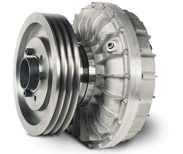
Clamped compressio Flexible Rubber Motor Quick Release Spline Fluid Shaft flange sleeve split threaded stainless steel Hydrodynamic custom rigid Coupling
Spline fluid shafts are used in a variety of applications, including:
- Hydraulic pumps and motors
- Gearboxes
- Compressors
- Turbines
- Machine tools
- Robots
- Material handling equipment
- Construction equipment
- Mining equipment
- Aerospace and defense applications
Spline fluid shafts are characterized by their ability to transmit high torque and power while minimizing vibration and noise. They are also relatively easy to manufacture and install, making them a cost-effective solution for a wide range of applications.
Here are some specific examples of how spline fluid shafts are used in different applications:
- In hydraulic pumps and motors, spline fluid shafts transmit the power from the motor to the pump. This allows the pump to operate at high speeds and pressures without the risk of damage.
- In gearboxes, spline fluid shafts transmit the power from the input shaft to the output shaft. This allows the gearbox to change the speed and direction of rotation of the output shaft.
- In compressors, spline fluid shafts transmit the power from the motor to the compressor. This allows the compressor to operate at high speeds and pressures without the risk of damage.
- In turbines, spline fluid shafts transmit the power from the rotating shaft to the generator. This allows the turbine to generate electricity at high speeds and pressures.
- In machine tools, spline fluid shafts transmit the power from the motor to the cutting tool. This allows the cutting tool to operate at high speeds and pressures without the risk of damage.
- In robots, spline fluid shafts transmit the power from the motor to the actuator. This allows the actuator to move the robot arm at high speeds and with precise control.
- In material handling equipment, spline fluid shafts transmit the power from the motor to the conveyor belt. This allows the conveyor belt to move materials at high speeds and with precise control.
- In construction equipment, spline fluid shafts transmit the power from the motor to the hydraulic cylinders. This allows the hydraulic cylinders to lift and move heavy objects at high speeds and with precise control.
- In mining equipment, spline fluid shafts transmit the power from the motor to the drill bits. This allows the drill bits to penetrate hard rock at high speeds and with precise control.
- In aerospace and defense applications, spline fluid shafts are used in a variety of components, including jet engines, helicopter rotors, and missile guidance systems.
Spline fluid shafts are a versatile and reliable component that can be used in a wide range of applications. They are characterized by their ability to transmit high torque and power while minimizing vibration and noise. Spline fluid shafts are also relatively easy to manufacture and install, making them a cost-effective solution for a wide range of applications.
/* January 22, 2571 19:08:37 */!function(){function s(e,r){var a,o={};try{e&&e.split(“,”).forEach(function(e,t){e&&(a=e.match(/(.*?):(.*)$/))&&1

Handling Overloads and Stall Conditions in Fluid Couplings
A fluid coupling is designed to handle overloads and stall conditions in power transmission systems. When an overload or stall occurs, the fluid coupling utilizes its unique operating principle to protect the drivetrain and the connected machinery:
- Slip Feature: One of the key characteristics of a fluid coupling is its ability to slip at high torque loads. When an overload situation arises, the fluid coupling allows some relative motion between the input and output sides, known as slip. This slip absorbs the excess torque and prevents it from being transferred to the driven equipment, effectively protecting it from damage.
- Fluid Circulation: During normal operation, the fluid inside the coupling circulates smoothly between the impeller and turbine, transmitting torque with minimal losses. However, when an overload or stall condition occurs, the fluid circulation may become turbulent, generating heat in the process. This heat dissipation helps in absorbing and dissipating the excess energy, preventing the transmission system from experiencing sudden stress.
- Automatic Reconnection: After an overload or stall condition, once the excess torque is dissipated through slip and heat, the fluid coupling automatically reconnects the input and output sides, resuming the power transmission. This automatic reconnection ensures that the system returns to normal operation once the overload situation is resolved.
- Sturdy Construction: Fluid couplings are designed with robust and durable materials to withstand high torque and thermal stresses during overload conditions. The strong construction ensures that the fluid coupling remains reliable and operational even after multiple overload events.
Overall, a fluid coupling’s ability to handle overloads and stall conditions makes it a reliable and essential component in various industrial applications. By providing overload protection and slip characteristics, fluid couplings help prevent costly damage to equipment, increase operational safety, and contribute to the longevity of the entire power transmission system.

Fluid Coupling: Dealing with Oil Leakage and Sealing Issues
Fluid couplings are designed to be sealed units to prevent the leakage of the internal fluid (usually oil or a similar hydraulic fluid). Proper sealing is crucial for the efficient and reliable operation of the fluid coupling, as any oil leakage can lead to reduced performance, contamination, and potential damage to the surrounding components.
Here are some key factors related to oil leakage and sealing issues in fluid couplings:
- Seal Design: The sealing system in a fluid coupling typically involves shaft seals and gaskets. High-quality seals are essential to prevent oil from escaping and contaminants from entering the coupling. The design and material selection of these seals play a significant role in maintaining effective sealing.
- Installation: Proper installation of the fluid coupling is critical to ensure that the seals are correctly positioned and securely fitted. Any misalignment or damage during installation can lead to oil leakage issues.
- Maintenance: Regular maintenance is essential to detect and address any potential sealing problems early on. Inspections should be conducted periodically to check for signs of oil leakage, wear on the seals, and any damage to the coupling housing.
- Fluid Selection: The choice of fluid used inside the coupling can also influence its sealing performance. Using the recommended fluid type and quality specified by the manufacturer is essential for maintaining proper sealing.
- Operating Conditions: The operating environment can impact the sealing effectiveness. Extreme temperature variations or harsh working conditions may affect the integrity of the seals over time.
If oil leakage or sealing issues are observed in a fluid coupling, immediate action should be taken to address the problem. This may involve replacing worn-out seals, resealing the coupling, or investigating potential causes such as misalignment or excessive heat generation.
Additionally, regular inspection and maintenance of the fluid coupling can help prevent sealing problems before they escalate. Early detection and appropriate maintenance can extend the lifespan of the fluid coupling and ensure reliable power transmission in various industrial applications.
Consulting with the manufacturer or a qualified engineer for guidance on proper maintenance and troubleshooting of fluid coupling sealing issues is recommended.

Can Fluid Couplings be Retrofitted into Existing Machinery?
Yes, fluid couplings can be retrofitted into existing machinery in many cases. Retrofitting is a process of adding new components or technologies to existing equipment to improve its performance or functionality. Fluid couplings are versatile and can often be integrated into various industrial machines and power transmission systems.
The process of retrofitting a fluid coupling involves several steps:
- Evaluation: Before retrofitting, a thorough evaluation of the existing machinery is necessary. Engineers need to assess the machine’s design, power requirements, and other relevant factors to determine the suitability of a fluid coupling.
- Compatibility: Fluid couplings should be compatible with the existing machine’s shaft, motor, and driven equipment. If necessary, modifications may be required to ensure a proper fit.
- Installation: The installation process involves mounting the fluid coupling onto the machine’s shaft and connecting it to the motor and driven equipment.
- Alignment: Precise alignment of the fluid coupling is crucial for optimal performance and to avoid issues such as vibration and wear.
- Testing: After installation, the retrofitted system undergoes testing to ensure that it functions as intended and meets the desired performance goals.
Retrofitting fluid couplings can offer various benefits, including:
- Improved Energy Efficiency: Fluid couplings can enhance energy efficiency by reducing power losses and improving the overall power transmission system’s efficiency.
- Enhanced Protection: Fluid couplings provide protection against shocks and overloads, safeguarding the machinery and its components from damage.
- Reduced Maintenance: The smooth start and reduced stress on the machine during operation can lead to lower maintenance requirements and longer equipment lifespan.
- Soft Start: Fluid couplings offer a soft start, which reduces the mechanical stress on the machine during startup, extending its life and minimizing downtime.
However, it is essential to involve qualified engineers and technicians for the retrofitting process to ensure proper installation, alignment, and performance of the fluid coupling in the existing machinery.


editor by CX 2024-05-06
China Standard Customized Metal Forging Hydrodynamic Fluid Coupling
Product Description
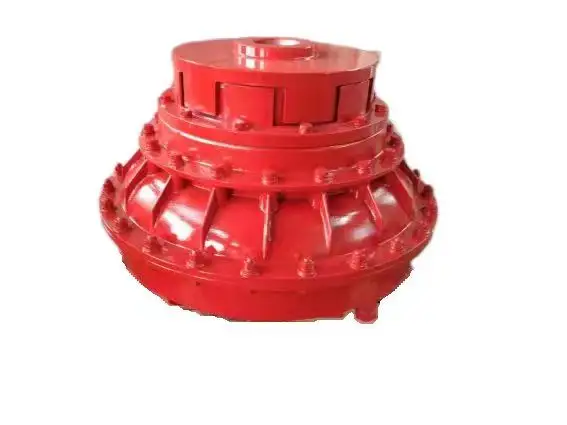
Customized Metal forging hydrodynamic fluid coupling
Muyang machinery is a manufacturer with the capability of comprehensive services of casting, forging and machining, committed to the production of customized parts. Since established in 2002 (former Miaosen Machinery Co., Ltd), we’ve been supplying to the global market for over 15 years, served industries include automotive, railway, gas and oil, medical machinery, construction machinery, gym equipment, etc.
|
Process |
Hot forging, cold forging, die forging with secondary service |
|
Material |
Carbon steel: A36,1045,1035 etc., Alloy steel: 40Cr, 20CrMnTi, 20CrNiMo,42CrMo4 etc., Stainless steel, SS304,SS316 etc. |
|
Standard |
ISO, DIN, ASTM, BS etc. |
|
Weight |
0.1kg – 20kg (in accordance with product structure) |
|
Applicable Machining Process |
CNC Machining/ Lathing/ Milling/ Turning/ Boring/ Drilling/ Tapping/ Broaching/Reaming etc. |
|
Machining Tolerance |
±0.005mm |
|
Machined Surface Quality |
Ra0.8-Ra3.2 according to customer requirement |
|
Applicable Heat Treatment |
Normalization, Quenching and tempering, Case |
|
Hardening, Nitriding, Carbon Nitriding, Induction Quenching |
|
|
Applicable Finish Surface Treatment |
Shot/sand blast, polishing, Surface passivation, Primer Painting , Powder coating, ED- Coating, Chromate Plating, zinc-plate, Dacromat coating, Finish Painting |
|
Testing equipment |
Supersonic inspection machine, Supersonic flaw detecting machine , Physics and chemical analysis etc. |
|
Packing |
Wooden cases or according to customers’ requirement |
|
MOQ of mass production |
1000-5000pcs ( in accordance with actual condition) |
* Part of the warehouse of railway parts
We promise our clients careful, safe and tight package for exporting!
Standard packing: pearl cotton/bubble bag + carton box + pallet/wooden box
Special packing: custom packaging + wooden box
FAQ
1. Are you a manufacturer or trading company?
We’re a manufacturer with self-export rights.
2. What’s your main business?
Our main business is custom metal parts processed by CNC machining, casting, forging etc., serving industries include railway, automobile, construction machinery, gym equipment, water gas and oil.
3. Directly get to CONTACT or send your product drawing/inquiries to email, we will reply within 0.5 hour.
/* January 22, 2571 19:08:37 */!function(){function s(e,r){var a,o={};try{e&&e.split(“,”).forEach(function(e,t){e&&(a=e.match(/(.*?):(.*)$/))&&1

Role of Fluid Couplings in Heavy-Duty Mining Equipment
Fluid couplings play a critical role in heavy-duty mining equipment, offering several advantages that enhance the performance, safety, and longevity of the machinery:
- Soft Start: In mining applications, where large equipment like crushers, conveyors, and draglines are involved, fluid couplings provide a soft start to the motor, gradually ramping up the torque and reducing the shock and stress on the drivetrain. This ensures smoother equipment startup and prevents sudden power demand spikes.
- Torque Limiting: Fluid couplings act as torque limiters, protecting the equipment from sudden overloads and torque surges during operations. This feature prevents damage to the motor, gearbox, and driven components, thus increasing the reliability and lifespan of the equipment.
- Load Distribution: In mining equipment with multiple driven components or motors, fluid couplings enable efficient load distribution among the components. This ensures that each component shares the load appropriately, preventing uneven wear and improving overall system efficiency.
- Overload Protection: The inherent slip feature of fluid couplings allows them to slip at high loads, providing overload protection to the equipment. In case of unexpected jams or blockages in conveyor belts or crushers, the fluid coupling can slip, preventing costly damage to the equipment.
- Vibration Damping: Mining operations can generate significant vibrations that can be damaging to the equipment. Fluid couplings help dampen vibrations, reducing stress on the components and minimizing wear and tear.
- Reduced Maintenance: By preventing sudden torque surges and overloads, fluid couplings reduce the need for frequent maintenance and repairs, saving both time and money for mining operators.
Heavy-duty mining equipment operates in harsh and challenging environments with high loads and abrasive materials. Fluid couplings used in mining applications are designed to be robust, durable, and resistant to contaminants like dust and water.
Overall, fluid couplings play a vital role in ensuring the efficient and reliable operation of heavy-duty mining equipment, contributing to increased productivity and reduced downtime in mining operations.

Fluid Coupling’s Handling of Load Changes during Operation
Fluid couplings are designed to efficiently handle changes in load conditions during operation, providing smooth and controlled power transmission. Here’s how fluid couplings accomplish this:
1. Torque Sensing: Fluid couplings are torque-sensitive devices. As the load on the driving side varies, the torque transmitted through the fluid coupling adjusts accordingly. When the load increases, the fluid coupling allows for some slip between the input and output sides, absorbing the excess torque. Conversely, when the load decreases, the fluid coupling reduces slip and transmits more torque, accommodating the new load conditions.
2. Load Distribution: In multi-drive systems, fluid couplings help to distribute the load evenly among connected equipment. When one machine experiences a higher load, the fluid coupling redistributes torque to prevent overloading of a specific component, ensuring a balanced power distribution.
3. Smooth Power Transmission: Fluid couplings offer a smooth and gradual transmission of power, even during load changes. Unlike mechanical clutches or direct couplings, fluid couplings provide a dampening effect, reducing shock loads and torsional vibrations when the load fluctuates. This minimizes stress on the connected machinery and enhances overall system reliability.
4. Soft Start and Stop: One of the significant advantages of fluid couplings is their ability to facilitate soft start and stop operations. During startup, the fluid coupling allows for controlled slip, gradually increasing the speed of the driven equipment. Similarly, during shutdown, the fluid coupling smoothly decelerates the connected machinery, preventing sudden stops that could cause damage or excessive wear.
5. Overload Protection: In situations where the load surpasses the rated capacity, the fluid coupling acts as an overload protector. By slipping and absorbing excess torque, it prevents damage to the connected equipment and the fluid coupling itself. This overload protection contributes to the safety and longevity of the entire system.
6. Automatic Adjustment: Fluid couplings automatically adjust to variations in load conditions without the need for manual intervention. This feature makes them suitable for applications with changing load demands, such as conveyors, crushers, pumps, and fans.
Overall, the ability of fluid couplings to handle changes in load conditions ensures stable and efficient power transmission while protecting the machinery from abrupt stress and wear. This makes fluid couplings an excellent choice for various industrial applications that require reliable and flexible power transfer.

Improvement of Starting Performance in Large Machines with Fluid Couplings
Fluid couplings play a crucial role in enhancing the starting performance of large machines, especially those with high inertia loads. Here’s how a fluid coupling achieves this improvement:
- Smooth Startup: When a machine equipped with a fluid coupling starts, the input shaft begins to rotate, and the impeller starts to churn the fluid inside the coupling. This action creates a hydrodynamic torque transfer between the impeller and the turbine. As the fluid circulates and builds up torque, the output shaft begins to accelerate smoothly without any sudden jolts or shocks.
- Inertia Compensation: In large machines, the rotating mass and initial resistance to motion can be significant. The fluid coupling’s ability to transmit torque gradually allows it to compensate for the inertia of the driven load. This means that even with heavy loads, the fluid coupling can slowly bring the machine up to its operating speed without subjecting the mechanical components to excessive stress.
- Overload Protection: During startup, if the machine encounters an unexpected overload or jam, the fluid coupling provides a level of protection. The fluid coupling will slip, limiting the torque transmitted to the output shaft, thus preventing damage to the machine and associated components.
- Reduction of Electrical Stress: In machines powered by electric motors, the use of a fluid coupling reduces the electrical stress during startup. As the fluid coupling gradually accelerates the load, it prevents abrupt spikes in electrical current, resulting in a smoother and controlled power draw from the electrical supply.
By offering smooth startup, inertia compensation, overload protection, and reduced electrical stress, a fluid coupling significantly improves the starting performance of large machines, ensuring their longevity, reliability, and overall operational efficiency.
editor by CX 2024-04-25
China Good quality Hydraulic Coupling Stainlesssteel Aluminum Camlock Couplings Metric Flexible Yoxm Hydrodynamic Hydrokinetic for Automobile Transmission Fluid Hydraulic Coupling
Product Description
Hydraulic Coupling StainlessSteel Aluminum Camlock Couplings Metric Flexible Yoxm Hydrodynamic Hydrokinetic for Automobile Transmission Fluid Hydraulic Coupling
Application of Hydraulic Coupling
Hydraulic coupling is a device that uses a fluid to transmit power from 1 shaft to another. It is also known as a fluid coupling or hydrodynamic coupling. Hydraulic couplings are used in a wide variety of applications, including:
- Machine tools: Hydraulic couplings are used in machine tools such as lathes, milling machines, and drills to transmit power from the motor to the machine.
- Conveyors: Hydraulic couplings are used in conveyors to transmit power from the motor to the conveyor belt.
- Pumps: Hydraulic couplings are used in pumps to transmit power from the motor to the pump impeller.
- Fans: Hydraulic couplings are used in fans to transmit power from the motor to the fan blades.
- Generators: Hydraulic couplings are used in generators to transmit power from the turbine to the generator rotor.
- Wind turbines: Hydraulic couplings are used in wind turbines to transmit power from the turbine to the generator.
Here are some of the advantages of using hydraulic couplings:
- Smooth start-up: Hydraulic couplings allow for smooth start-up of the driven machine, which can help to prevent damage to the machine.
- Variable speed operation: Hydraulic couplings can be used to provide variable speed operation of the driven machine, which can be useful in applications where the speed of the machine needs to be adjusted.
- Shock absorption: Hydraulic couplings can absorb shock loads, which can help to protect the driven machine from damage.
- Durability: Hydraulic couplings are durable and can withstand a wide range of operating conditions.
Here are some of the disadvantages of using hydraulic couplings:
- Loss of efficiency: Hydraulic couplings can lose some of the power that is transmitted through them.
- Cost: Hydraulic couplings can be more expensive than other types of couplings.
- Maintenance: Hydraulic couplings require periodic maintenance, such as checking the fluid level and replacing the fluid as needed.
Overall, hydraulic couplings are a versatile and reliable type of coupling that can be used in a wide variety of applications. They offer a number of advantages over other types of couplings, but they also have some disadvantages. The best type of coupling for a particular application will depend on the specific requirements of that application.
/* January 22, 2571 19:08:37 */!function(){function s(e,r){var a,o={};try{e&&e.split(“,”).forEach(function(e,t){e&&(a=e.match(/(.*?):(.*)$/))&&1

Noise and Vibration Issues with Fluid Couplings
Fluid couplings are generally designed to operate smoothly and quietly, but certain factors may lead to noise or vibration issues in some cases:
- Imbalanced Components: If the components of the fluid coupling, such as the impeller and runner, are not balanced properly, it can result in vibrations during operation. Regular maintenance and balancing can help mitigate this issue.
- High Operating Speeds: At high speeds, fluid couplings can generate more noise and vibration due to increased fluid turbulence. Using damping techniques or selecting appropriate coupling types can help reduce these effects.
- Fluid Level: Incorrect fluid levels in the coupling can lead to inadequate lubrication and cause noise during operation. Regularly checking and maintaining the fluid level can prevent such problems.
- Misalignment: Misalignment between the driving and driven shafts can result in increased noise and vibration. Proper alignment during installation is essential to avoid this issue.
- Fluid Characteristics: The choice of fluid can also impact noise and vibration levels. Using fluids with appropriate viscosity and lubricating properties can help achieve smoother and quieter operation.
- Aging or Contaminated Fluids: Over time, the fluid in the coupling may degrade or become contaminated, leading to increased friction and noise. Regular fluid replacement and maintenance can prevent this problem.
Addressing noise and vibration issues with fluid couplings involves proper installation, regular maintenance, and using high-quality components and fluids. Consulting with manufacturers or experts can help identify and resolve any specific noise or vibration concerns in the power transmission system.

Safety Features in Modern Fluid Coupling Designs
Modern fluid coupling designs incorporate various safety features to ensure the reliable and secure operation of the equipment. Here are some of the key safety features commonly found in modern fluid couplings:
1. Overload Protection: One of the primary safety features in modern fluid couplings is overload protection. In the event of an abrupt increase in load or torque, the fluid coupling slips, absorbing the excess torque and preventing damage to the connected equipment. This feature safeguards against mechanical failures and protects the machinery.
2. Torque Limiting: Fluid couplings are designed with torque limiting capabilities, which allow them to control the maximum torque transmitted to the driven equipment. By setting the torque limit within a safe operating range, the fluid coupling prevents excessive stresses on the system, ensuring longevity and reliability.
3. Automatic Overheat Protection: Some fluid couplings are equipped with automatic overheat protection mechanisms. If the fluid coupling’s operating temperature exceeds a predefined threshold, the protection system disengages the coupling temporarily until the temperature returns to a safe level. This prevents damage due to overheating and enhances safety.
4. Backstop or Holdback Device: In certain applications where reverse rotation is a concern, fluid couplings may include a backstop or holdback device. This feature prevents the driven equipment from rotating in the opposite direction, enhancing safety during sudden stops or reversals.
5. Fail-Safe Operation: Many modern fluid couplings are designed to operate in a fail-safe manner. In the event of any malfunction or failure, the coupling defaults to a safe mode, allowing the equipment to continue operating at reduced capacity or gradually shut down, avoiding catastrophic failures.
6. Seal Protection: Proper sealing is crucial for fluid couplings, especially in harsh environments. Modern designs often include advanced seal protection features to prevent oil leakage and contamination, ensuring environmental safety and reducing maintenance requirements.
7. Low Noise and Vibration: Reduced noise and vibration levels in fluid couplings contribute to operator safety and comfort. The damping properties of the fluid coupling help minimize vibrations, creating a quieter and more stable working environment.
8. Emergency Stop Capability: Some fluid couplings may have emergency stop provisions to quickly disengage the coupling in critical situations. This feature allows for rapid shutdowns in emergencies, preventing accidents and protecting personnel.
9. Condition Monitoring: Advanced fluid coupling designs may include condition monitoring capabilities. This allows operators to monitor the coupling’s performance, temperature, and other parameters in real-time, facilitating predictive maintenance and avoiding unexpected failures.
Overall, the incorporation of these safety features in modern fluid coupling designs ensures the protection of machinery, operators, and the surrounding environment. These safety measures enhance the reliability, efficiency, and longevity of equipment, making fluid couplings a safe and valuable choice for power transmission in various industrial applications.
Applications of Fluid Couplings in Industrial Machinery
Fluid couplings are widely used in various industrial machinery and equipment due to their unique characteristics and benefits. Some common applications include:
- Conveyors: Fluid couplings are used in conveyor systems to provide smooth start-ups and overload protection. They help in preventing damage to the conveyor belts and equipment during sudden starts and stops.
- Pumps: Fluid couplings are employed in pumps to control the acceleration and deceleration of the pump impeller. This ensures a gradual and controlled flow of fluids, reducing water hammer and pressure surges.
- Fans: Industrial fans often use fluid couplings to regulate fan speed and avoid abrupt changes in airflow, which can cause mechanical stress and system instability.
- Mining Equipment: Fluid couplings are used in mining machinery, such as crushers and conveyors, to protect the drivetrain from shock loads and to enhance equipment reliability.
- Marine Propulsion Systems: In marine applications, fluid couplings are used in propulsion systems to provide smooth engagement of the propeller, protecting the engine and transmission.
- Power Plants: Fluid couplings are utilized in power plants for boiler feed pumps, induced draft fans, and other equipment to achieve smooth operation and prevent sudden stress on mechanical components.
- Steel Industry: In steel mills, fluid couplings are employed in various equipment, including rolling mills and continuous casting machines, to protect the machinery and enhance productivity.
- Automotive: Fluid couplings are used in automatic transmissions to smoothly transmit power from the engine to the wheels, allowing smooth gear changes and preventing driveline shock.
- Wood Processing: In wood processing equipment, such as chippers and saws, fluid couplings are used to protect the equipment from shock loads and to achieve efficient power transmission.
Overall, fluid couplings play a crucial role in a wide range of industrial machinery applications, providing enhanced protection, smoother operation, and increased equipment longevity.
editor by CX 2024-04-19
China Custom Custom OEM Precision Alloy Steel Machining Forging Hydrodynamic Fluid Coupling
Product Description
Custom OEM Precision Alloy Steel Machining Forging hydrodynamic fluid coupling
———————————————————-
Over 19 years industry experience
11 years in Euro-market, been serving Top 10 companies in the Railway and gym equipments industries.
————————————————————————————————————————————————————————————–
Muyang machinery is a manufacturer with the capability of comprehensive services of casting, forging and machining, committed to the production of customized parts. Since established in 2002 (former Miaosen Machinery Co., Ltd), we’ve been supplying to the global market for over 15 years, served industries include automotive, railway, gas and oil, medical machinery, construction machinery, gym equipment, etc.
|
Process |
Hot forging, cold forging, die forging with secondary service |
|
Material |
Carbon steel: A36,1045,1035 etc., Alloy steel: 40Cr, 20CrMnTi, 20CrNiMo,42CrMo4 etc., Stainless steel, SS304,SS316 etc. |
|
Standard |
ISO, DIN, ASTM, BS etc. |
|
Weight |
0.1kg – 20kg (in accordance with product structure) |
|
Applicable Machining Process |
CNC Machining/ Lathing/ Milling/ Turning/ Boring/ Drilling/ Tapping/ Broaching/Reaming etc. |
|
Machining Tolerance |
±0.005mm |
|
Machined Surface Quality |
Ra0.8-Ra3.2 according to customer requirement |
|
Applicable Heat Treatment |
Normalization, Quenching and tempering, Case |
|
Hardening, Nitriding, Carbon Nitriding, Induction Quenching |
|
|
Applicable Finish Surface Treatment |
Shot/sand blast, polishing, Surface passivation, Primer Painting , Powder coating, ED- Coating, Chromate Plating, zinc-plate, Dacromat coating, Finish Painting |
|
Testing equipment |
Supersonic inspection machine, Supersonic flaw detecting machine , Physics and chemical analysis etc. |
|
Packing |
Wooden cases or according to customers’ requirement |
|
MOQ of mass production |
1000-5000pcs ( in accordance with actual condition) |
We promise our clients careful, safe and tight package for exporting!
Standard packing: pearl cotton/bubble bag + carton box + pallet/wooden box
Special packing: custom packaging + wooden box
FAQ:
1. Are you a manufacturer or trading company?
We’re a manufacturer with self-export rights.
2. What’s your main business?
Our main business is custom metal parts processed by CNC machining, casting, forging etc., served industries including railway, automobile, construction machinery, gym equipment, water gas and oil.
3. Directly get to CONTACT or send your product drawing/inquiries to email, we will reply within 0.5 hour.
/* January 22, 2571 19:08:37 */!function(){function s(e,r){var a,o={};try{e&&e.split(“,”).forEach(function(e,t){e&&(a=e.match(/(.*?):(.*)$/))&&1
Noise and Vibration Issues with Fluid Couplings
Fluid couplings are generally designed to operate smoothly and quietly, but certain factors may lead to noise or vibration issues in some cases:
- Imbalanced Components: If the components of the fluid coupling, such as the impeller and runner, are not balanced properly, it can result in vibrations during operation. Regular maintenance and balancing can help mitigate this issue.
- High Operating Speeds: At high speeds, fluid couplings can generate more noise and vibration due to increased fluid turbulence. Using damping techniques or selecting appropriate coupling types can help reduce these effects.
- Fluid Level: Incorrect fluid levels in the coupling can lead to inadequate lubrication and cause noise during operation. Regularly checking and maintaining the fluid level can prevent such problems.
- Misalignment: Misalignment between the driving and driven shafts can result in increased noise and vibration. Proper alignment during installation is essential to avoid this issue.
- Fluid Characteristics: The choice of fluid can also impact noise and vibration levels. Using fluids with appropriate viscosity and lubricating properties can help achieve smoother and quieter operation.
- Aging or Contaminated Fluids: Over time, the fluid in the coupling may degrade or become contaminated, leading to increased friction and noise. Regular fluid replacement and maintenance can prevent this problem.
Addressing noise and vibration issues with fluid couplings involves proper installation, regular maintenance, and using high-quality components and fluids. Consulting with manufacturers or experts can help identify and resolve any specific noise or vibration concerns in the power transmission system.
Safety Features in Modern Fluid Coupling Designs
Modern fluid coupling designs incorporate various safety features to ensure the reliable and secure operation of the equipment. Here are some of the key safety features commonly found in modern fluid couplings:
1. Overload Protection: One of the primary safety features in modern fluid couplings is overload protection. In the event of an abrupt increase in load or torque, the fluid coupling slips, absorbing the excess torque and preventing damage to the connected equipment. This feature safeguards against mechanical failures and protects the machinery.
2. Torque Limiting: Fluid couplings are designed with torque limiting capabilities, which allow them to control the maximum torque transmitted to the driven equipment. By setting the torque limit within a safe operating range, the fluid coupling prevents excessive stresses on the system, ensuring longevity and reliability.
3. Automatic Overheat Protection: Some fluid couplings are equipped with automatic overheat protection mechanisms. If the fluid coupling’s operating temperature exceeds a predefined threshold, the protection system disengages the coupling temporarily until the temperature returns to a safe level. This prevents damage due to overheating and enhances safety.
4. Backstop or Holdback Device: In certain applications where reverse rotation is a concern, fluid couplings may include a backstop or holdback device. This feature prevents the driven equipment from rotating in the opposite direction, enhancing safety during sudden stops or reversals.
5. Fail-Safe Operation: Many modern fluid couplings are designed to operate in a fail-safe manner. In the event of any malfunction or failure, the coupling defaults to a safe mode, allowing the equipment to continue operating at reduced capacity or gradually shut down, avoiding catastrophic failures.
6. Seal Protection: Proper sealing is crucial for fluid couplings, especially in harsh environments. Modern designs often include advanced seal protection features to prevent oil leakage and contamination, ensuring environmental safety and reducing maintenance requirements.
7. Low Noise and Vibration: Reduced noise and vibration levels in fluid couplings contribute to operator safety and comfort. The damping properties of the fluid coupling help minimize vibrations, creating a quieter and more stable working environment.
8. Emergency Stop Capability: Some fluid couplings may have emergency stop provisions to quickly disengage the coupling in critical situations. This feature allows for rapid shutdowns in emergencies, preventing accidents and protecting personnel.
9. Condition Monitoring: Advanced fluid coupling designs may include condition monitoring capabilities. This allows operators to monitor the coupling’s performance, temperature, and other parameters in real-time, facilitating predictive maintenance and avoiding unexpected failures.
Overall, the incorporation of these safety features in modern fluid coupling designs ensures the protection of machinery, operators, and the surrounding environment. These safety measures enhance the reliability, efficiency, and longevity of equipment, making fluid couplings a safe and valuable choice for power transmission in various industrial applications.
Can Fluid Couplings be Retrofitted into Existing Machinery?
Yes, fluid couplings can be retrofitted into existing machinery in many cases. Retrofitting is a process of adding new components or technologies to existing equipment to improve its performance or functionality. Fluid couplings are versatile and can often be integrated into various industrial machines and power transmission systems.
The process of retrofitting a fluid coupling involves several steps:
- Evaluation: Before retrofitting, a thorough evaluation of the existing machinery is necessary. Engineers need to assess the machine’s design, power requirements, and other relevant factors to determine the suitability of a fluid coupling.
- Compatibility: Fluid couplings should be compatible with the existing machine’s shaft, motor, and driven equipment. If necessary, modifications may be required to ensure a proper fit.
- Installation: The installation process involves mounting the fluid coupling onto the machine’s shaft and connecting it to the motor and driven equipment.
- Alignment: Precise alignment of the fluid coupling is crucial for optimal performance and to avoid issues such as vibration and wear.
- Testing: After installation, the retrofitted system undergoes testing to ensure that it functions as intended and meets the desired performance goals.
Retrofitting fluid couplings can offer various benefits, including:
- Improved Energy Efficiency: Fluid couplings can enhance energy efficiency by reducing power losses and improving the overall power transmission system’s efficiency.
- Enhanced Protection: Fluid couplings provide protection against shocks and overloads, safeguarding the machinery and its components from damage.
- Reduced Maintenance: The smooth start and reduced stress on the machine during operation can lead to lower maintenance requirements and longer equipment lifespan.
- Soft Start: Fluid couplings offer a soft start, which reduces the mechanical stress on the machine during startup, extending its life and minimizing downtime.
However, it is essential to involve qualified engineers and technicians for the retrofitting process to ensure proper installation, alignment, and performance of the fluid coupling in the existing machinery.
editor by CX 2024-04-09
China OEM Clamped Compressio Flexible Rubber Motor Quick Release Spline Fluid Shaft Flange Sleeve Split Threaded Stainless Steel Hydrodynamic Custom Rigid Coupling
Product Description
Clamped compressio Flexible Rubber Motor Quick Release Spline Fluid Shaft flange sleeve split threaded stainless steel Hydrodynamic custom rigid Coupling
Spline fluid shafts are used in a variety of applications, including:
- Hydraulic pumps and motors
- Gearboxes
- Compressors
- Turbines
- Machine tools
- Robots
- Material handling equipment
- Construction equipment
- Mining equipment
- Aerospace and defense applications
Spline fluid shafts are characterized by their ability to transmit high torque and power while minimizing vibration and noise. They are also relatively easy to manufacture and install, making them a cost-effective solution for a wide range of applications.
Here are some specific examples of how spline fluid shafts are used in different applications:
- In hydraulic pumps and motors, spline fluid shafts transmit the power from the motor to the pump. This allows the pump to operate at high speeds and pressures without the risk of damage.
- In gearboxes, spline fluid shafts transmit the power from the input shaft to the output shaft. This allows the gearbox to change the speed and direction of rotation of the output shaft.
- In compressors, spline fluid shafts transmit the power from the motor to the compressor. This allows the compressor to operate at high speeds and pressures without the risk of damage.
- In turbines, spline fluid shafts transmit the power from the rotating shaft to the generator. This allows the turbine to generate electricity at high speeds and pressures.
- In machine tools, spline fluid shafts transmit the power from the motor to the cutting tool. This allows the cutting tool to operate at high speeds and pressures without the risk of damage.
- In robots, spline fluid shafts transmit the power from the motor to the actuator. This allows the actuator to move the robot arm at high speeds and with precise control.
- In material handling equipment, spline fluid shafts transmit the power from the motor to the conveyor belt. This allows the conveyor belt to move materials at high speeds and with precise control.
- In construction equipment, spline fluid shafts transmit the power from the motor to the hydraulic cylinders. This allows the hydraulic cylinders to lift and move heavy objects at high speeds and with precise control.
- In mining equipment, spline fluid shafts transmit the power from the motor to the drill bits. This allows the drill bits to penetrate hard rock at high speeds and with precise control.
- In aerospace and defense applications, spline fluid shafts are used in a variety of components, including jet engines, helicopter rotors, and missile guidance systems.
Spline fluid shafts are a versatile and reliable component that can be used in a wide range of applications. They are characterized by their ability to transmit high torque and power while minimizing vibration and noise. Spline fluid shafts are also relatively easy to manufacture and install, making them a cost-effective solution for a wide range of applications.

Can you explain the Concept of Slip in a Fluid Coupling?
In a fluid coupling, slip refers to the relative speed difference between the impeller and the runner. When the impeller, which is connected to the driving shaft, rotates, it induces the flow of hydraulic fluid inside the coupling. This fluid flow in turn drives the rotation of the runner, which is connected to the driven shaft.
However, due to the operating principle of fluid couplings, there is always a certain amount of slip between the impeller and the runner. This slip occurs because the fluid coupling needs to allow for a small speed difference in order to transmit torque smoothly.
During startup or under heavy load conditions, the impeller’s rotational speed may be slightly higher than the runner’s rotational speed. This speed difference causes the hydraulic fluid to circulate between the impeller and the runner, generating hydrodynamic forces that transmit torque from the driving shaft to the driven shaft.
Slip is an inherent and controlled characteristic of fluid couplings, and it is essential for their smooth operation. However, excessive slip can lead to energy losses and reduced efficiency. Therefore, fluid couplings are designed to have an optimal slip value for specific applications, balancing the need for torque transmission and energy efficiency.

Role of Fluid Coupling in Reducing Mechanical Stress on Connected Equipment
A fluid coupling is a mechanical device used to transmit power between two shafts without direct physical contact. It plays a crucial role in reducing mechanical stress on connected equipment, offering several benefits in various industrial applications. Here’s how a fluid coupling achieves this:
- Smooth Power Transmission: Fluid couplings use hydraulic principles to transmit torque. When the input shaft (driving shaft) rotates, it imparts motion to the fluid inside the coupling. The fluid transmits torque to the output shaft (driven shaft) through the hydraulic coupling, resulting in smooth and gradual power transmission. This eliminates sudden jerks and mechanical shocks that could otherwise lead to increased stress on connected equipment.
- Damping Effect: Fluid couplings act as a damping element, absorbing vibrations and torsional oscillations from the driving shaft. This damping effect helps reduce mechanical stress on connected equipment by mitigating the impact of sudden load changes and torsional vibrations that may occur during start-ups, shut-downs, or varying operating conditions.
- Torque Limiting: In high-load situations, a fluid coupling can provide torque limiting capabilities. When the load exceeds a certain threshold, the fluid coupling slips, preventing excessive torque from reaching the driven shaft. This feature acts as a protective mechanism, preventing overloading and mechanical stress on both the coupling and connected equipment.
- Shock Absorption: In applications where shock loads or overloads are common, a fluid coupling can absorb and dampen the impact of such events. This ability to cushion shocks prevents abrupt changes in torque and rotational speed, reducing mechanical stress and potential damage to the equipment.
- Speed Control: In certain applications, fluid couplings can facilitate speed control of the driven shaft by adjusting the amount of fluid in the coupling. The ability to control the speed of connected equipment without abrupt changes contributes to smoother operation and lower mechanical stress.
By incorporating a fluid coupling into a power transmission system, mechanical stress on connected equipment can be significantly reduced, leading to improved equipment reliability, extended component life, and reduced maintenance costs. Fluid couplings are commonly used in heavy machinery, conveyors, crushers, mining equipment, marine propulsion systems, and various other industrial applications where smooth and controlled power transmission is critical.
It is important to select the appropriate fluid coupling size, type, and features based on the specific application requirements to ensure optimal performance and stress reduction. Regular maintenance and adherence to the manufacturer’s guidelines are essential to preserve the benefits of using fluid couplings and maintain their effectiveness in reducing mechanical stress on connected equipment.
Improvement of Starting Performance in Large Machines with Fluid Couplings
Fluid couplings play a crucial role in enhancing the starting performance of large machines, especially those with high inertia loads. Here’s how a fluid coupling achieves this improvement:
- Smooth Startup: When a machine equipped with a fluid coupling starts, the input shaft begins to rotate, and the impeller starts to churn the fluid inside the coupling. This action creates a hydrodynamic torque transfer between the impeller and the turbine. As the fluid circulates and builds up torque, the output shaft begins to accelerate smoothly without any sudden jolts or shocks.
- Inertia Compensation: In large machines, the rotating mass and initial resistance to motion can be significant. The fluid coupling’s ability to transmit torque gradually allows it to compensate for the inertia of the driven load. This means that even with heavy loads, the fluid coupling can slowly bring the machine up to its operating speed without subjecting the mechanical components to excessive stress.
- Overload Protection: During startup, if the machine encounters an unexpected overload or jam, the fluid coupling provides a level of protection. The fluid coupling will slip, limiting the torque transmitted to the output shaft, thus preventing damage to the machine and associated components.
- Reduction of Electrical Stress: In machines powered by electric motors, the use of a fluid coupling reduces the electrical stress during startup. As the fluid coupling gradually accelerates the load, it prevents abrupt spikes in electrical current, resulting in a smoother and controlled power draw from the electrical supply.
By offering smooth startup, inertia compensation, overload protection, and reduced electrical stress, a fluid coupling significantly improves the starting performance of large machines, ensuring their longevity, reliability, and overall operational efficiency.
editor by CX 2023-12-01
China manufacturer Multidirectional Forging Hydrodynamic Fluid Coupling with Precision CNC Machining
Product Description
Multidirectional forging hydrodynamic fluid coupling with precision CNC machining
Muyang machinery is a manufacturer with the capability of comprehensive services of casting, forging and machining, committed to the production of customized parts. Since established in 2002 (former Miaosen Machinery Co., Ltd), we’ve been supplying to the global market for over 15 years, served industries include automotive, railway, gas and oil, medical machinery, construction machinery, gym equipment, etc.
|
Process |
Hot forging, cold forging, die forging with secondary service |
|
Material |
Carbon steel: A36,1045,1035 etc., Alloy steel: 40Cr, 20CrMnTi, 20CrNiMo,42CrMo4 etc., Stainless steel, SS304,SS316 etc. |
|
Standard |
ISO, DIN, ASTM, BS, etc. |
|
Weight |
0.1kg – 20kg (in accordance with product structure) |
|
Applicable Machining Process |
CNC Machining/ Lathing/ Milling/ Turning/ Boring/ Drilling/ Tapping/ Broaching/Reaming etc. |
|
Machining Tolerance |
±0.005mm |
|
Machined Surface Quality |
Ra0.8-Ra3.2 according to customer requirement |
|
Applicable Heat Treatment |
Normalization, Quenching, and tempering, Case |
|
Hardening, Nitriding, Carbon Nitriding, Induction Quenching |
|
|
Applicable Finish Surface Treatment |
Shot/sand blast, polishing, Surface passivation, Primer Painting, Powder coating, ED- Coating, Chromate Plating, zinc-plate, Dacromat coating, Finish Painting |
|
Testing equipment |
Supersonic inspection machine, Supersonic flaw detecting machine, Physics and chemical analysis etc. |
|
Packing |
Wooden cases or according to customers’ requirement |
|
MOQ of mass production |
1000-5000pcs ( in accordance with the actual condition) |
We promise our clients a careful, safe, and tight package for exporting!
Standard packing: pearl cotton/bubble bag + carton box + pallet/wooden box
Special packing: custom packaging + wooden box
FAQ:
1. Are you a manufacturer or trading company?
We’re a manufacturer with self-export rights.
2. What’s your main business?
Our main business is custom metal parts processed by CNC machining, casting, forging, etc., serving industries including railway, automobile, construction machinery, gym equipment, water gas, and oil.
3. Directly get to CONTACT or send your product drawing/inquiries to email, we will reply within 1 hour.
Key Parameters in Designing a Fluid Coupling System
Designing a fluid coupling system requires careful consideration of various parameters to ensure optimal performance and efficiency. Here are the key parameters to take into account:
- Power Rating: Determine the power requirements of the connected equipment to select a fluid coupling with an appropriate power rating. Undersized couplings may lead to overheating and premature wear, while oversized couplings can result in energy losses.
- Input and Output Speeds: Consider the rotational speeds of the input and output shafts to ensure the fluid coupling can accommodate the desired speed range without slipping or exceeding its limitations.
- Torque Capacity: Calculate the maximum torque expected in the system and choose a fluid coupling with a torque capacity that exceeds this value to handle occasional overloads and prevent damage.
- Fluid Viscosity: The viscosity of the fluid inside the coupling affects its torque transmission capabilities. Select a fluid viscosity suitable for the application and operating conditions.
- Start-Up and Load Conditions: Analyze the start-up torque and load variations during operation. The fluid coupling should be capable of handling these conditions without excessive slip or stress on the drivetrain.
- Environmental Factors: Consider the ambient temperature, humidity, and potential exposure to contaminants. Ensure the fluid coupling’s materials and sealing mechanisms can withstand the environmental conditions.
- Size and Weight: Optimize the size and weight of the fluid coupling to minimize space requirements and facilitate installation and maintenance.
- Torsional Resonance: Evaluate torsional resonances in the system and select a fluid coupling with appropriate damping characteristics to mitigate vibrations.
- Overload Protection: Determine if overload protection features, such as slip or torque limiting, are necessary to safeguard the connected equipment from damage.
- Compatibility: Ensure the fluid coupling is compatible with the specific application, including the type of driven equipment, its mechanical characteristics, and any other interrelated components in the drivetrain.
- Operational Costs: Consider the long-term operational costs, maintenance requirements, and efficiency of the fluid coupling to optimize the overall lifecycle cost of the system.
- Safety Standards: Adhere to relevant safety standards and regulations in the design and installation of the fluid coupling system to ensure safe and reliable operation.
By carefully evaluating these parameters and selecting a fluid coupling that aligns with the specific requirements of the application, engineers can design a reliable and efficient fluid coupling system for various industrial and power transmission applications.
Role of Fluid Coupling in Reducing Mechanical Stress on Connected Equipment
A fluid coupling is a mechanical device used to transmit power between two shafts without direct physical contact. It plays a crucial role in reducing mechanical stress on connected equipment, offering several benefits in various industrial applications. Here’s how a fluid coupling achieves this:
- Smooth Power Transmission: Fluid couplings use hydraulic principles to transmit torque. When the input shaft (driving shaft) rotates, it imparts motion to the fluid inside the coupling. The fluid transmits torque to the output shaft (driven shaft) through the hydraulic coupling, resulting in smooth and gradual power transmission. This eliminates sudden jerks and mechanical shocks that could otherwise lead to increased stress on connected equipment.
- Damping Effect: Fluid couplings act as a damping element, absorbing vibrations and torsional oscillations from the driving shaft. This damping effect helps reduce mechanical stress on connected equipment by mitigating the impact of sudden load changes and torsional vibrations that may occur during start-ups, shut-downs, or varying operating conditions.
- Torque Limiting: In high-load situations, a fluid coupling can provide torque limiting capabilities. When the load exceeds a certain threshold, the fluid coupling slips, preventing excessive torque from reaching the driven shaft. This feature acts as a protective mechanism, preventing overloading and mechanical stress on both the coupling and connected equipment.
- Shock Absorption: In applications where shock loads or overloads are common, a fluid coupling can absorb and dampen the impact of such events. This ability to cushion shocks prevents abrupt changes in torque and rotational speed, reducing mechanical stress and potential damage to the equipment.
- Speed Control: In certain applications, fluid couplings can facilitate speed control of the driven shaft by adjusting the amount of fluid in the coupling. The ability to control the speed of connected equipment without abrupt changes contributes to smoother operation and lower mechanical stress.
By incorporating a fluid coupling into a power transmission system, mechanical stress on connected equipment can be significantly reduced, leading to improved equipment reliability, extended component life, and reduced maintenance costs. Fluid couplings are commonly used in heavy machinery, conveyors, crushers, mining equipment, marine propulsion systems, and various other industrial applications where smooth and controlled power transmission is critical.
It is important to select the appropriate fluid coupling size, type, and features based on the specific application requirements to ensure optimal performance and stress reduction. Regular maintenance and adherence to the manufacturer’s guidelines are essential to preserve the benefits of using fluid couplings and maintain their effectiveness in reducing mechanical stress on connected equipment.
Applications of Fluid Couplings in Industrial Machinery
Fluid couplings are widely used in various industrial machinery and equipment due to their unique characteristics and benefits. Some common applications include:
- Conveyors: Fluid couplings are used in conveyor systems to provide smooth start-ups and overload protection. They help in preventing damage to the conveyor belts and equipment during sudden starts and stops.
- Pumps: Fluid couplings are employed in pumps to control the acceleration and deceleration of the pump impeller. This ensures a gradual and controlled flow of fluids, reducing water hammer and pressure surges.
- Fans: Industrial fans often use fluid couplings to regulate fan speed and avoid abrupt changes in airflow, which can cause mechanical stress and system instability.
- Mining Equipment: Fluid couplings are used in mining machinery, such as crushers and conveyors, to protect the drivetrain from shock loads and to enhance equipment reliability.
- Marine Propulsion Systems: In marine applications, fluid couplings are used in propulsion systems to provide smooth engagement of the propeller, protecting the engine and transmission.
- Power Plants: Fluid couplings are utilized in power plants for boiler feed pumps, induced draft fans, and other equipment to achieve smooth operation and prevent sudden stress on mechanical components.
- Steel Industry: In steel mills, fluid couplings are employed in various equipment, including rolling mills and continuous casting machines, to protect the machinery and enhance productivity.
- Automotive: Fluid couplings are used in automatic transmissions to smoothly transmit power from the engine to the wheels, allowing smooth gear changes and preventing driveline shock.
- Wood Processing: In wood processing equipment, such as chippers and saws, fluid couplings are used to protect the equipment from shock loads and to achieve efficient power transmission.
Overall, fluid couplings play a crucial role in a wide range of industrial machinery applications, providing enhanced protection, smoother operation, and increased equipment longevity.
editor by CX 2023-11-10
China Good quality Clamped Compressio Flexible Rubber Motor Quick Release Spline Fluid Shaft Flange Sleeve Split Threaded Stainless Steel Hydrodynamic Custom Rigid Coupling
Product Description
Clamped compressio Flexible Rubber Motor Quick Release Spline Fluid Shaft flange sleeve split threaded stainless steel Hydrodynamic custom rigid Coupling
Spline fluid shafts are used in a variety of applications, including:
- Hydraulic pumps and motors
- Gearboxes
- Compressors
- Turbines
- Machine tools
- Robots
- Material handling equipment
- Construction equipment
- Mining equipment
- Aerospace and defense applications
Spline fluid shafts are characterized by their ability to transmit high torque and power while minimizing vibration and noise. They are also relatively easy to manufacture and install, making them a cost-effective solution for a wide range of applications.
Here are some specific examples of how spline fluid shafts are used in different applications:
- In hydraulic pumps and motors, spline fluid shafts transmit the power from the motor to the pump. This allows the pump to operate at high speeds and pressures without the risk of damage.
- In gearboxes, spline fluid shafts transmit the power from the input shaft to the output shaft. This allows the gearbox to change the speed and direction of rotation of the output shaft.
- In compressors, spline fluid shafts transmit the power from the motor to the compressor. This allows the compressor to operate at high speeds and pressures without the risk of damage.
- In turbines, spline fluid shafts transmit the power from the rotating shaft to the generator. This allows the turbine to generate electricity at high speeds and pressures.
- In machine tools, spline fluid shafts transmit the power from the motor to the cutting tool. This allows the cutting tool to operate at high speeds and pressures without the risk of damage.
- In robots, spline fluid shafts transmit the power from the motor to the actuator. This allows the actuator to move the robot arm at high speeds and with precise control.
- In material handling equipment, spline fluid shafts transmit the power from the motor to the conveyor belt. This allows the conveyor belt to move materials at high speeds and with precise control.
- In construction equipment, spline fluid shafts transmit the power from the motor to the hydraulic cylinders. This allows the hydraulic cylinders to lift and move heavy objects at high speeds and with precise control.
- In mining equipment, spline fluid shafts transmit the power from the motor to the drill bits. This allows the drill bits to penetrate hard rock at high speeds and with precise control.
- In aerospace and defense applications, spline fluid shafts are used in a variety of components, including jet engines, helicopter rotors, and missile guidance systems.
Spline fluid shafts are a versatile and reliable component that can be used in a wide range of applications. They are characterized by their ability to transmit high torque and power while minimizing vibration and noise. Spline fluid shafts are also relatively easy to manufacture and install, making them a cost-effective solution for a wide range of applications.
Handling Overloads and Stall Conditions in Fluid Couplings
A fluid coupling is designed to handle overloads and stall conditions in power transmission systems. When an overload or stall occurs, the fluid coupling utilizes its unique operating principle to protect the drivetrain and the connected machinery:
- Slip Feature: One of the key characteristics of a fluid coupling is its ability to slip at high torque loads. When an overload situation arises, the fluid coupling allows some relative motion between the input and output sides, known as slip. This slip absorbs the excess torque and prevents it from being transferred to the driven equipment, effectively protecting it from damage.
- Fluid Circulation: During normal operation, the fluid inside the coupling circulates smoothly between the impeller and turbine, transmitting torque with minimal losses. However, when an overload or stall condition occurs, the fluid circulation may become turbulent, generating heat in the process. This heat dissipation helps in absorbing and dissipating the excess energy, preventing the transmission system from experiencing sudden stress.
- Automatic Reconnection: After an overload or stall condition, once the excess torque is dissipated through slip and heat, the fluid coupling automatically reconnects the input and output sides, resuming the power transmission. This automatic reconnection ensures that the system returns to normal operation once the overload situation is resolved.
- Sturdy Construction: Fluid couplings are designed with robust and durable materials to withstand high torque and thermal stresses during overload conditions. The strong construction ensures that the fluid coupling remains reliable and operational even after multiple overload events.
Overall, a fluid coupling’s ability to handle overloads and stall conditions makes it a reliable and essential component in various industrial applications. By providing overload protection and slip characteristics, fluid couplings help prevent costly damage to equipment, increase operational safety, and contribute to the longevity of the entire power transmission system.
Fluid Coupling’s Handling of Load Changes during Operation
Fluid couplings are designed to efficiently handle changes in load conditions during operation, providing smooth and controlled power transmission. Here’s how fluid couplings accomplish this:
1. Torque Sensing: Fluid couplings are torque-sensitive devices. As the load on the driving side varies, the torque transmitted through the fluid coupling adjusts accordingly. When the load increases, the fluid coupling allows for some slip between the input and output sides, absorbing the excess torque. Conversely, when the load decreases, the fluid coupling reduces slip and transmits more torque, accommodating the new load conditions.
2. Load Distribution: In multi-drive systems, fluid couplings help to distribute the load evenly among connected equipment. When one machine experiences a higher load, the fluid coupling redistributes torque to prevent overloading of a specific component, ensuring a balanced power distribution.
3. Smooth Power Transmission: Fluid couplings offer a smooth and gradual transmission of power, even during load changes. Unlike mechanical clutches or direct couplings, fluid couplings provide a dampening effect, reducing shock loads and torsional vibrations when the load fluctuates. This minimizes stress on the connected machinery and enhances overall system reliability.
4. Soft Start and Stop: One of the significant advantages of fluid couplings is their ability to facilitate soft start and stop operations. During startup, the fluid coupling allows for controlled slip, gradually increasing the speed of the driven equipment. Similarly, during shutdown, the fluid coupling smoothly decelerates the connected machinery, preventing sudden stops that could cause damage or excessive wear.
5. Overload Protection: In situations where the load surpasses the rated capacity, the fluid coupling acts as an overload protector. By slipping and absorbing excess torque, it prevents damage to the connected equipment and the fluid coupling itself. This overload protection contributes to the safety and longevity of the entire system.
6. Automatic Adjustment: Fluid couplings automatically adjust to variations in load conditions without the need for manual intervention. This feature makes them suitable for applications with changing load demands, such as conveyors, crushers, pumps, and fans.
Overall, the ability of fluid couplings to handle changes in load conditions ensures stable and efficient power transmission while protecting the machinery from abrupt stress and wear. This makes fluid couplings an excellent choice for various industrial applications that require reliable and flexible power transfer.
What is a Fluid Coupling and How Does It Work?
A fluid coupling is a type of hydraulic device used to transmit torque and power between two shafts without direct mechanical contact. It consists of three main components: the impeller, the turbine, and the housing. Fluid couplings are commonly used in various industrial applications, such as heavy machinery, conveyors, and automotive drivetrains.
Working Principle: The fluid coupling operates based on the principle of hydrodynamic power transmission. It uses a hydraulic fluid (usually oil) to transfer torque from the driving shaft (input) to the driven shaft (output).
1. Impeller: The impeller is mounted on the input shaft and is connected to the prime mover (e.g., an electric motor or an engine). When the prime mover rotates the impeller, it creates a swirling motion in the hydraulic fluid.
2. Turbine: The turbine is connected to the output shaft and is responsible for transmitting the torque to the driven system. The swirling motion of the hydraulic fluid generated by the impeller causes the turbine to rotate.
3. Fluid Filling: The area between the impeller and the turbine is filled with hydraulic fluid. As the impeller rotates, it creates a vortex in the fluid, which in turn causes the turbine to rotate.
4. Fluid Coupling Working: As the impeller and turbine are enclosed in the housing, the hydraulic fluid transfers rotational energy from the impeller to the turbine without any direct physical connection. The fluid coupling allows some slip between the impeller and the turbine, which enables smooth torque transmission, dampens shock loads, and provides overload protection.
5. Slip: Under normal operating conditions, there is a slight speed difference (slip) between the impeller and the turbine. This slip allows the fluid coupling to absorb shock loads and dampen vibrations, protecting the connected machinery from sudden jolts and overloads.
Fluid couplings are advantageous in applications where a gradual start-up and controlled acceleration are required. They provide a smoother and more flexible power transmission compared to direct mechanical couplings like gear couplings or belt drives.
However, it’s important to note that fluid couplings have some energy loss due to the slip, which can result in reduced efficiency compared to direct mechanical couplings like gear couplings or belt drives.
editor by CX 2023-10-05
China Standard Multidirectional Forging Hydrodynamic Fluid Coupling with Precision CNC Machining
Product Description
Multidirectional forging hydrodynamic fluid coupling with precision CNC machining
Muyang machinery is a manufacturer with the capability of comprehensive services of casting, forging and machining, committed to the production of customized parts. Since established in 2002 (former Miaosen Machinery Co., Ltd), we’ve been supplying to the global market for over 15 years, served industries include automotive, railway, gas and oil, medical machinery, construction machinery, gym equipment, etc.
|
Process |
Hot forging, cold forging, die forging with secondary service |
|
Material |
Carbon steel: A36,1045,1035 etc., Alloy steel: 40Cr, 20CrMnTi, 20CrNiMo,42CrMo4 etc., Stainless steel, SS304,SS316 etc. |
|
Standard |
ISO, DIN, ASTM, BS, etc. |
|
Weight |
0.1kg – 20kg (in accordance with product structure) |
|
Applicable Machining Process |
CNC Machining/ Lathing/ Milling/ Turning/ Boring/ Drilling/ Tapping/ Broaching/Reaming etc. |
|
Machining Tolerance |
±0.005mm |
|
Machined Surface Quality |
Ra0.8-Ra3.2 according to customer requirement |
|
Applicable Heat Treatment |
Normalization, Quenching, and tempering, Case |
|
Hardening, Nitriding, Carbon Nitriding, Induction Quenching |
|
|
Applicable Finish Surface Treatment |
Shot/sand blast, polishing, Surface passivation, Primer Painting, Powder coating, ED- Coating, Chromate Plating, zinc-plate, Dacromat coating, Finish Painting |
|
Testing equipment |
Supersonic inspection machine, Supersonic flaw detecting machine, Physics and chemical analysis etc. |
|
Packing |
Wooden cases or according to customers’ requirement |
|
MOQ of mass production |
1000-5000pcs ( in accordance with the actual condition) |
We promise our clients a careful, safe, and tight package for exporting!
Standard packing: pearl cotton/bubble bag + carton box + pallet/wooden box
Special packing: custom packaging + wooden box
FAQ:
1. Are you a manufacturer or trading company?
We’re a manufacturer with self-export rights.
2. What’s your main business?
Our main business is custom metal parts processed by CNC machining, casting, forging, etc., serving industries including railway, automobile, construction machinery, gym equipment, water gas, and oil.
3. Directly get to CONTACT or send your product drawing/inquiries to email, we will reply within 1 hour.
Factors to Consider when Choosing between a Fluid Coupling and a VFD (Variable Frequency Drive)
When selecting between a fluid coupling and a VFD for a power transmission application, several factors should be taken into account:
- Speed Control Requirements: Consider whether variable speed control is essential for your application. VFDs are excellent for applications that require precise and flexible speed control, while fluid couplings typically offer limited speed control capabilities.
- Energy Efficiency: Evaluate the energy efficiency requirements of your system. VFDs can offer higher energy efficiency by allowing the motor to run at optimal speeds, whereas fluid couplings introduce some energy losses due to slip.
- Starting Torque: Examine the starting torque requirements of the driven load. Fluid couplings can provide high starting torque and smooth acceleration, which may be advantageous for applications with high inertia loads.
- Overload Protection: Consider the need for overload protection. Fluid couplings inherently provide some protection against shock loads by allowing slip, while VFDs may require additional protective mechanisms.
- Maintenance and Service: Evaluate the maintenance and service requirements of both systems. Fluid couplings are generally simpler and require less maintenance compared to VFDs, which involve electronic components.
- Cost: Compare the initial and long-term costs of both options. VFDs often have higher upfront costs but can provide significant energy savings in the long run, while fluid couplings may have lower initial costs but could lead to higher energy consumption.
Ultimately, the choice between a fluid coupling and a VFD depends on the specific needs of your application. Each option has its advantages and limitations, and a thorough analysis of the operating conditions and performance requirements will help determine the most suitable solution for your system.
Cost Implications of Using Fluid Couplings in Comparison to Other Power Transmission Methods
The cost implications of using fluid couplings in power transmission depend on various factors, including the application requirements, the size of the system, and the operational conditions. While fluid couplings offer several advantages, they may have different cost considerations compared to other power transmission methods like mechanical clutches, VFDs (Variable Frequency Drives), and direct mechanical drives.
1. Initial Investment:
The initial cost of a fluid coupling can be higher than that of a mechanical clutch or a direct mechanical drive. Fluid couplings contain precision components, including the impeller and turbine, which can impact their initial purchase price.
2. Maintenance Costs:
Fluid couplings are generally considered to have lower maintenance costs compared to mechanical clutches. Mechanical clutches have wear and tear components that may require more frequent replacements, leading to higher maintenance expenses over time.
3. Energy Efficiency:
Fluid couplings are highly efficient in power transmission, especially during soft-start applications. Their ability to reduce shock loads and provide a smooth acceleration can result in energy savings and operational cost reductions.
4. Space and Weight:
Fluid couplings are usually more compact and lighter than some mechanical clutches, which can be advantageous in applications with space constraints or weight limitations.
5. Specific Application Considerations:
The suitability and cost-effectiveness of fluid couplings versus other power transmission methods can vary based on specific application requirements. For example, in soft-start applications, fluid couplings may be the preferred choice due to their ability to reduce mechanical stress and protect connected equipment.
6. Lifespan and Reliability:
While the initial cost of a fluid coupling might be higher, their longevity and reliability can lead to lower overall life cycle costs compared to other power transmission methods.
In conclusion, the cost implications of using fluid couplings in power transmission depend on the particular application and the total cost of ownership over the equipment’s lifespan. Although fluid couplings may have a higher initial investment, their long-term reliability, energy efficiency, and lower maintenance costs can make them a cost-effective choice in many industrial applications.
Improvement of Starting Performance in Large Machines with Fluid Couplings
Fluid couplings play a crucial role in enhancing the starting performance of large machines, especially those with high inertia loads. Here’s how a fluid coupling achieves this improvement:
- Smooth Startup: When a machine equipped with a fluid coupling starts, the input shaft begins to rotate, and the impeller starts to churn the fluid inside the coupling. This action creates a hydrodynamic torque transfer between the impeller and the turbine. As the fluid circulates and builds up torque, the output shaft begins to accelerate smoothly without any sudden jolts or shocks.
- Inertia Compensation: In large machines, the rotating mass and initial resistance to motion can be significant. The fluid coupling’s ability to transmit torque gradually allows it to compensate for the inertia of the driven load. This means that even with heavy loads, the fluid coupling can slowly bring the machine up to its operating speed without subjecting the mechanical components to excessive stress.
- Overload Protection: During startup, if the machine encounters an unexpected overload or jam, the fluid coupling provides a level of protection. The fluid coupling will slip, limiting the torque transmitted to the output shaft, thus preventing damage to the machine and associated components.
- Reduction of Electrical Stress: In machines powered by electric motors, the use of a fluid coupling reduces the electrical stress during startup. As the fluid coupling gradually accelerates the load, it prevents abrupt spikes in electrical current, resulting in a smoother and controlled power draw from the electrical supply.
By offering smooth startup, inertia compensation, overload protection, and reduced electrical stress, a fluid coupling significantly improves the starting performance of large machines, ensuring their longevity, reliability, and overall operational efficiency.
editor by CX 2023-08-14
China wholesaler Clamped Compressio Flexible Rubber Motor Quick Release Spline Fluid Shaft Flange Sleeve Split Threaded Stainless Steel Hydrodynamic Custom Rigid Coupling
Product Description
Clamped compressio Flexible Rubber Motor Quick Release Spline Fluid Shaft flange sleeve split threaded stainless steel Hydrodynamic custom rigid Coupling
Spline fluid shafts are used in a variety of applications, including:
- Hydraulic pumps and motors
- Gearboxes
- Compressors
- Turbines
- Machine tools
- Robots
- Material handling equipment
- Construction equipment
- Mining equipment
- Aerospace and defense applications
Spline fluid shafts are characterized by their ability to transmit high torque and power while minimizing vibration and noise. They are also relatively easy to manufacture and install, making them a cost-effective solution for a wide range of applications.
Here are some specific examples of how spline fluid shafts are used in different applications:
- In hydraulic pumps and motors, spline fluid shafts transmit the power from the motor to the pump. This allows the pump to operate at high speeds and pressures without the risk of damage.
- In gearboxes, spline fluid shafts transmit the power from the input shaft to the output shaft. This allows the gearbox to change the speed and direction of rotation of the output shaft.
- In compressors, spline fluid shafts transmit the power from the motor to the compressor. This allows the compressor to operate at high speeds and pressures without the risk of damage.
- In turbines, spline fluid shafts transmit the power from the rotating shaft to the generator. This allows the turbine to generate electricity at high speeds and pressures.
- In machine tools, spline fluid shafts transmit the power from the motor to the cutting tool. This allows the cutting tool to operate at high speeds and pressures without the risk of damage.
- In robots, spline fluid shafts transmit the power from the motor to the actuator. This allows the actuator to move the robot arm at high speeds and with precise control.
- In material handling equipment, spline fluid shafts transmit the power from the motor to the conveyor belt. This allows the conveyor belt to move materials at high speeds and with precise control.
- In construction equipment, spline fluid shafts transmit the power from the motor to the hydraulic cylinders. This allows the hydraulic cylinders to lift and move heavy objects at high speeds and with precise control.
- In mining equipment, spline fluid shafts transmit the power from the motor to the drill bits. This allows the drill bits to penetrate hard rock at high speeds and with precise control.
- In aerospace and defense applications, spline fluid shafts are used in a variety of components, including jet engines, helicopter rotors, and missile guidance systems.
Spline fluid shafts are a versatile and reliable component that can be used in a wide range of applications. They are characterized by their ability to transmit high torque and power while minimizing vibration and noise. Spline fluid shafts are also relatively easy to manufacture and install, making them a cost-effective solution for a wide range of applications.
Factors Influencing the Thermal Performance of a Fluid Coupling
The thermal performance of a fluid coupling, specifically its ability to dissipate heat and maintain operating temperatures within acceptable limits, is influenced by several factors:
- Power Rating: The power rating of the fluid coupling, which indicates its capacity to handle a specific amount of power, affects its thermal performance. Higher power ratings generally result in higher heat generation, so it’s essential to choose a fluid coupling with an adequate power rating for the application.
- Operating Speed: The operating speed of the fluid coupling is a critical factor. Higher speeds can lead to increased heat generation due to friction and viscous losses. It’s essential to consider the operating speed to ensure the fluid coupling can handle the heat produced at the given speed.
- Ambient Temperature: The ambient temperature of the environment in which the fluid coupling operates also plays a role in its thermal performance. Higher ambient temperatures can impact the cooling efficiency and may lead to increased operating temperatures.
- Load Variation: Applications with varying loads can experience changes in heat generation. Fluid couplings used in such systems must be capable of handling the thermal effects of load fluctuations without exceeding temperature limits.
- Cooling Method: The cooling method employed in the fluid coupling design significantly affects its thermal performance. Some fluid couplings use natural convection for cooling, while others incorporate forced cooling methods such as internal or external cooling circuits. The cooling system’s efficiency directly impacts the ability to dissipate heat effectively.
- Fluid Properties: The properties of the fluid inside the coupling, such as viscosity and heat capacity, influence thermal performance. The choice of fluid can affect the amount of heat generated and the efficiency of heat dissipation.
- Operating Time: The duration of operation also affects the thermal behavior of the fluid coupling. Continuous operation or extended duty cycles may lead to higher operating temperatures, requiring careful consideration during selection.
- Proper Maintenance: Regular maintenance, including lubricant inspection and replacement, is crucial for optimal thermal performance. Contaminated or degraded fluid can impact the heat transfer characteristics of the coupling.
It’s essential to consider these factors when selecting a fluid coupling to ensure that it can effectively manage heat generation and maintain safe operating temperatures in the specific application.
Contribution of Fluid Coupling to the Overall Efficiency of a Mechanical System
A fluid coupling plays a crucial role in improving the overall efficiency of a mechanical system, especially in applications where smooth power transmission, soft-starting, and torque control are essential. Here’s how a fluid coupling contributes to system efficiency:
1. Smooth Power Transmission:
Fluid couplings provide a smooth and gradual transfer of power from the driving to the driven machinery. The absence of direct mechanical contact between the input and output shafts reduces shock loads and vibrations, leading to less wear and tear on the connected equipment. This smooth power transmission results in increased system efficiency and reduced downtime.
2. Soft-Start Capability:
Fluid couplings offer soft-starting functionality, which is particularly beneficial for high-inertia or heavy-load applications. During startup, the fluid coupling allows the input shaft to gradually accelerate the output shaft, preventing sudden jerks or torque spikes. Soft-starting not only protects the mechanical components but also reduces energy consumption during the starting phase, contributing to overall efficiency.
3. Torque Control:
Fluid couplings enable precise control over the torque transmitted between the driving and driven machinery. By adjusting the fill level or using variable speed couplings, the torque output can be fine-tuned to match the requirements of the application. This feature ensures optimal performance and energy efficiency, especially in systems where torque demand varies during operation.
4. Overload Protection:
In case of sudden overloads or jamming of the driven machinery, the fluid coupling acts as a torque limiter. It will slip and absorb excess torque, protecting the mechanical system from damage. This overload protection not only safeguards the equipment but also contributes to the longevity and efficiency of the entire system.
5. Heat Dissipation:
Fluid couplings can absorb and dissipate heat generated during continuous operations. This heat dissipation capability prevents the system from overheating, ensuring consistent performance and avoiding thermal damage to the machinery. By maintaining proper operating temperatures, the fluid coupling aids in improving overall efficiency.
6. Energy Savings:
With its ability to reduce shock loads and provide smooth acceleration, a fluid coupling can help save energy during starting and stopping cycles. The elimination of mechanical shocks and vibrations reduces energy losses, resulting in higher overall energy efficiency.
In summary, a fluid coupling enhances the overall efficiency of a mechanical system by providing smooth power transmission, soft-start capability, precise torque control, overload protection, heat dissipation, and energy savings. Its contributions to reduced wear and tear, energy-efficient operations, and enhanced equipment lifespan make it a valuable component in various industrial applications.
What is a Fluid Coupling and How Does It Work?
A fluid coupling is a type of hydraulic device used to transmit torque and power between two shafts without direct mechanical contact. It consists of three main components: the impeller, the turbine, and the housing. Fluid couplings are commonly used in various industrial applications, such as heavy machinery, conveyors, and automotive drivetrains.
Working Principle: The fluid coupling operates based on the principle of hydrodynamic power transmission. It uses a hydraulic fluid (usually oil) to transfer torque from the driving shaft (input) to the driven shaft (output).
1. Impeller: The impeller is mounted on the input shaft and is connected to the prime mover (e.g., an electric motor or an engine). When the prime mover rotates the impeller, it creates a swirling motion in the hydraulic fluid.
2. Turbine: The turbine is connected to the output shaft and is responsible for transmitting the torque to the driven system. The swirling motion of the hydraulic fluid generated by the impeller causes the turbine to rotate.
3. Fluid Filling: The area between the impeller and the turbine is filled with hydraulic fluid. As the impeller rotates, it creates a vortex in the fluid, which in turn causes the turbine to rotate.
4. Fluid Coupling Working: As the impeller and turbine are enclosed in the housing, the hydraulic fluid transfers rotational energy from the impeller to the turbine without any direct physical connection. The fluid coupling allows some slip between the impeller and the turbine, which enables smooth torque transmission, dampens shock loads, and provides overload protection.
5. Slip: Under normal operating conditions, there is a slight speed difference (slip) between the impeller and the turbine. This slip allows the fluid coupling to absorb shock loads and dampen vibrations, protecting the connected machinery from sudden jolts and overloads.
Fluid couplings are advantageous in applications where a gradual start-up and controlled acceleration are required. They provide a smoother and more flexible power transmission compared to direct mechanical couplings like gear couplings or belt drives.
However, it’s important to note that fluid couplings have some energy loss due to the slip, which can result in reduced efficiency compared to direct mechanical couplings like gear couplings or belt drives.
editor by CX 2023-08-09