Product Description
Product Description
|
Product name |
Chain coupling |
|||
|
Material |
Carbon steel material |
|||
|
Structure |
Roller chain+sprocket+cover |
|||
|
Size |
KC3012, KC4012, KC4014, KC4016, KC5014, KC5016, KC5018, KC6018, KC6571, KC6571, KC8018, KC8571, KC8571, KC1571, KC12018, KC12571, KC16018, KC16571, KC20018, KC20571, KC24026 |
|||
|
Other type |
Flexible coupling |
|||
|
Application |
Shaft transmission |
|||
|
Feature |
High performance, light weight, convenient assembly |
|||
Packaging & Shipping
Company Profile
ZheJiang Haorongshengye Electrical Equipment Co., Ltd.
1. Was founded in 2008
2. Our Principle:
“Credibility Supremacy, and Customer First”
3. Our Promise:
“High quality products, and Excellent Service”
4. Our Value:
“Being Honesty, Doing the Best, and Long-lasting Development”
5. Our Aim:
“Develop to be a leader in the power transmission parts industry in the world”
|
6.Our services: |
1).Competitive price |
|||
|
2).High quality products |
||||
|
3).OEM service or can customized according to your drawings |
||||
|
4).Reply your inquiry in 24 hours |
||||
|
5).Professional technical team 24 hours online service |
||||
|
6).Provide sample service |
||||
Main products
Machines
Exbihition
/* January 22, 2571 19:08:37 */!function(){function s(e,r){var a,o={};try{e&&e.split(“,”).forEach(function(e,t){e&&(a=e.match(/(.*?):(.*)$/))&&1
How does the chain size affect the performance of a chain coupling?
The chain size has a significant impact on the performance of a chain coupling. The size of the chain refers to the physical dimensions of the roller chain used in the coupling, including the pitch, roller diameter, and width. Here are some key ways in which the chain size affects the performance of a chain coupling:
- Torque Capacity: The chain size directly affects the torque capacity of the chain coupling. Larger chain sizes are generally capable of transmitting higher torque loads due to their increased contact area and greater strength. Smaller chain sizes, on the other hand, have lower torque capacities and are suitable for applications with lighter torque requirements.
- Speed Capability: The chain size also influences the speed capability of the chain coupling. Larger chains can typically handle higher rotational speeds without experiencing issues such as excessive vibration or centrifugal forces. Smaller chain sizes may have limitations in terms of maximum allowable speeds and may not be suitable for high-speed applications.
- Service Life: The selection of an appropriate chain size is crucial for achieving the desired service life of the chain coupling. If the chain is undersized for the application, it may experience premature wear, fatigue, and ultimately fail under the operating conditions. Conversely, using an oversized chain may result in unnecessary costs, increased weight, and reduced efficiency.
- Space Constraints: The physical size of the chain can also impact the overall dimensions and installation requirements of the chain coupling. Larger chain sizes may require more space for proper installation, including clearance for the chain links and sprockets. In applications with limited space, choosing a smaller chain size may be necessary to ensure proper fit and operation.
- Compatibility: The chain size should be compatible with the sprockets and other components of the chain coupling. It is important to ensure that the chain and sprockets are designed to work together, with matching dimensions and tooth profiles. Using an incompatible chain size can lead to poor engagement, increased wear, and reduced overall performance.
When selecting the appropriate chain size for a chain coupling, it is essential to consider the specific requirements of the application, including torque, speed, space limitations, and compatibility with other components. Consulting the manufacturer’s recommendations and guidelines is crucial to ensure the optimal chain size selection for the desired performance, reliability, and longevity of the chain coupling.
What are the key components of a chain coupling?
A chain coupling consists of several key components that work together to transmit power and accommodate misalignments. Here are the main components of a chain coupling:
- Sprockets: Sprockets are the toothed wheels that engage with the chain. They are typically made of steel or other durable materials and have specially designed teeth that mesh with the chain rollers. The sprockets provide the driving and driven connections, transmitting torque from one shaft to another.
- Roller Chain: The roller chain is a series of interconnected links with rollers between them. It is looped around the sprockets, with the rollers engaging with the sprocket teeth. The roller chain transfers the rotational motion from the driving sprocket to the driven sprocket, allowing power transmission between the shafts.
- Connecting Pins: Connecting pins are used to join the links of the roller chain together, forming a continuous loop. These pins are inserted through the pin holes in the chain links and secured with retaining clips or other fasteners. They ensure the integrity and strength of the chain.
- Bushings or Bearings: Bushings or bearings are used to support the shafts and allow them to rotate smoothly within the chain coupling. They are typically inserted into the bores of the sprockets and provide a low-friction interface between the shaft and the coupling components.
- Guard or Cover: In some chain couplings, a guard or cover is added to enclose the sprockets and chain. This serves as a protective barrier, preventing contact with moving parts and reducing the risk of accidents or injuries. The guard or cover also helps to contain lubrication and protect the chain from contaminants.
- Lubrication: Lubrication is essential for the smooth operation and longevity of a chain coupling. Proper lubrication reduces friction, wear, and noise. Lubricants, such as chain oil or grease, are applied to the chain and sprockets to minimize frictional losses and prevent premature wear.
These components work together to provide a reliable and efficient power transmission in chain couplings. The sprockets engage with the roller chain, and as one sprocket rotates, it drives the chain, causing the other sprocket and the connected shaft to rotate. The roller chain and its components, along with lubrication, allow for flexibility and compensation of misalignment between the shafts.
What are the disadvantages of chain couplings?
-
Backlash: Chain couplings can exhibit a certain degree of backlash or play due to the clearances between the chain rollers and the sprocket teeth. This can result in reduced precision and accuracy in applications where precise motion control is required.
-
Noise and Vibration: The engagement between the chain and sprockets can generate noise and vibration during operation. This can be problematic in applications where noise reduction is important or where excessive vibration can affect the performance or integrity of the machinery.
-
Maintenance Requirements: While chain couplings are relatively easy to maintain, they still require regular attention. Lubrication of the chain and sprockets is essential to reduce wear and friction. Additionally, periodic inspection and adjustment of chain tension are necessary to ensure proper operation. Neglecting maintenance tasks can lead to premature wear, decreased efficiency, and potential coupling failure.
-
Space and Weight: Chain couplings occupy a certain amount of space due to the presence of sprockets and the length of the chain. In applications with space constraints, the size of the coupling may limit its usability. Additionally, the weight of the coupling components can be a consideration in applications where weight reduction is important.
-
Limitations in High-Speed Applications: Chain couplings may have limitations in high-speed applications. At high rotational speeds, the centrifugal forces acting on the chain and sprockets can increase, potentially causing stress and reducing the efficiency of the coupling. In such cases, alternative coupling designs, such as gear or flexible shaft couplings, may be more suitable.
-
Wear and Service Life: Like any mechanical component, chain couplings are subject to wear over time. The chain and sprockets can experience gradual wear and elongation, requiring eventual replacement. The service life of a chain coupling depends on factors such as the operating conditions, maintenance practices, and the quality of the components used.
While chain couplings offer several advantages, it is important to consider these disadvantages and evaluate their impact based on the specific application requirements. Proper maintenance, periodic inspection, and careful consideration of design factors can help mitigate these disadvantages and ensure optimal performance and longevity of the chain coupling.


editor by CX 2024-05-17
China factory Newest Sliver Rigid Fluid Diaphragm Coupling
Product Description
Diaphragm Coupling Shaft Coupling (JMI)
JM Series Diaphragm Coupling of flexible metal flexible coupling, which rely on the metal diaphragm to transmit torque from the main connection, motivation, has the advantages of elastic damping and no lubrication, no noise, is an ideal product for replacing the gear coupling and coupling current. It can compensate the axial, radial and angular deviation caused by the manufacturing error, installation error, bearing deformation and the change of temperature rise.
The main characteristics of JM Series Diaphragm Coupling:
1.Compensation 2 axis misalignment of the ability, and tooth type coupling can be much more than a double angle displacement, radial displacement of the small, flexible, allowing a certain axial, radial and angular displacement.
2. Obvious damping effect, no noise, no wear and tear.
3.High transmission efficiency, up to 99.86%. Especially suitable for medium and high speed high power transmission.
4.Adapt to high temperature (-80+300) and harsh environment, and can be in shock, vibration, safety and dynamic conditions.
5.Simple structure, light weight, small size, convenient assembly and disassembly. Without moving the machine can be disassembled (with intermediate type), no need of lubrication.
6.Accurately convey the rotational speed, the operation has not turned bad, can be used for the transmission of precision machinery.
JM series diaphragm flexible coupling is widely used in machinery and equipment industry, metallurgy, mines, petroleum, chemical, electric power, shipbuilding, lifting transport, textile, light industry, agricultural machinery, printing machinery and water pump, fan, etc. in the transmission of power machine.
|
||||||||||||||||||||||||||||||||||||||||||||||||||||||||||||||||||||||||||||||||||||||||||||||||||||||||||||||||||||||||||||||||||||||||||||||||||||||||||||||||||||||||||||||||||||||||||||||||||||||||||||||||||||||||||||||||||||||||||||||||||||||||||||||||||||||||||||||||||||||||||||||||||||||||||||||||||||||||||||||||||||||||||||||||||||||||||||||||||||||||||||||||||||||||
Detailed Photos
Company Profile
HangZhou CHINAMFG Machinery Manufacturing Co., Ltd. is a high-tech enterprise specializing in the design and manufacture of various types of coupling. There are 86 employees in our company, including 2 senior engineers and no fewer than 20 mechanical design and manufacture, heat treatment, welding, and other professionals.
Advanced and reasonable process, complete detection means. Our company actively introduces foreign advanced technology and equipment, on the basis of the condition, we make full use of the advantage and do more research and innovation. Strict to high quality and operate strictly in accordance with the ISO9000 quality certification system standard mode.
Our company supplies different kinds of products. High quality and reasonable price. We stick to the principle of “quality first, service first, continuous improvement and innovation to meet the customers” for the management and “zero defect, zero complaints” as the quality objective.
Our Services
1. Design Services
Our design team has experience in Cardan shafts relating to product design and development. If you have any needs for your new product or wish to make further improvements, we are here to offer our support.
2. Product Services
raw materials → Cutting → Forging →Rough machining →Shot blasting →Heat treatment →Testing →Fashioning →Cleaning→ Assembly→Packing→Shipping
3. Samples Procedure
We could develop the sample according to your requirement and amend the sample constantly to meet your need.
4. Research & Development
We usually research the new needs of the market and develop new models when there are new cars in the market.
5. Quality Control
Every step should be a particular test by Professional Staff according to the standard of ISO9001 and TS16949.
FAQ
Q 1: Are you a trading company or a manufacturer?
A: We are a professional manufacturer specializing in manufacturing
various series of couplings.
Q 2:Can you do OEM?
Yes, we can. We can do OEM & ODM for all customers with customized PDF or AI format artwork.
Q 3:How long is your delivery time?
Generally, it is 20-30 days if the goods are not in stock. It is according to quantity.
Q 4: Do you provide samples? Is it free or extra?
Yes, we could offer the sample but not for free. Actually, we have an excellent price principle, when you make the bulk order the cost of the sample will be deducted.
Q 5: How long is your warranty?
A: Our Warranty is 12 months under normal circumstances.
Q 6: What is the MOQ?
A: Usually our MOQ is 1pcs.
Q 7: Do you have inspection procedures for coupling?
A:100% self-inspection before packing.
Q 8: Can I have a visit to your factory before the order?
A: Sure, welcome to visit our factory.
Q 9: What’s your payment?
A:1) T/T.
♦Contact Us
Web: huadingcoupling
Add: No.11 HangZhou Road,Chengnan park,HangZhou City,ZheJiang Province,China
/* January 22, 2571 19:08:37 */!function(){function s(e,r){var a,o={};try{e&&e.split(“,”).forEach(function(e,t){e&&(a=e.match(/(.*?):(.*)$/))&&1

Fluid Couplings in Conjunction with Electric Motors
Yes, fluid couplings can be used in conjunction with electric motors to provide a reliable and efficient power transmission solution. When coupled with an electric motor, the fluid coupling serves as a mechanical torque converter, enabling smooth start-ups and gradual acceleration of the driven load.
The combination of a fluid coupling and an electric motor offers several advantages:
- Soft Start: When the electric motor is switched on, it accelerates gradually as the fluid coupling allows the torque to build up slowly. This soft start feature reduces mechanical stress on the driven equipment and minimizes the impact on the electrical supply, preventing voltage drops and surges.
- Overload Protection: Fluid couplings can automatically disengage when the load exceeds a certain threshold, providing overload protection to both the motor and the driven equipment. This feature helps prevent damage to the system during abrupt load changes or stall conditions.
- Vibration Damping: The fluid in the coupling acts as a damping medium, reducing vibration and shock loads during start-ups and sudden load changes. This contributes to smoother operation and extends the lifespan of the connected machinery.
- Energy Efficiency: By facilitating soft start and controlling torque transmission, fluid couplings improve the energy efficiency of the system. They reduce the inrush current during start-up, which can lead to significant energy savings in the long run.
- Variable Speed Control: In some configurations, fluid couplings can be combined with Variable Frequency Drives (VFDs) to provide variable speed control. The VFD regulates the speed of the electric motor, while the fluid coupling ensures smooth and controlled power transmission to the driven equipment.
Overall, the combination of a fluid coupling with an electric motor is a versatile solution that finds applications in various industries. It allows for reliable and controlled power transmission, protecting both the motor and the driven equipment while improving system efficiency.

Real-World Case Studies: Improved Performance with Fluid Couplings
Fluid couplings have been widely adopted in various industries, and numerous real-world case studies demonstrate their positive impact on performance and efficiency. Here are a few examples:
Case Study 1: Mining Conveyor System
In a large mining operation, a conveyor system used to transport heavy loads of ore experienced frequent starts and stops due to fluctuating material supply. The abrupt starting and stopping led to significant wear and tear on the conveyor components, causing frequent breakdowns and maintenance downtime.
After installing fluid couplings at critical points in the conveyor system, the soft start and stop capability of the fluid couplings significantly reduced the mechanical stress during operation. This led to a smoother material flow, reduced conveyor wear, and extended equipment life. Additionally, the fluid couplings’ overload protection feature prevented damage to the conveyor during peak loads, ensuring uninterrupted production.
Case Study 2: Marine Propulsion System
In a marine vessel equipped with traditional direct drive systems, the crew faced challenges in maneuvering the ship efficiently. The fixed propeller arrangement made it challenging to control the vessel’s speed and direction accurately, leading to increased fuel consumption and decreased maneuverability.
By retrofitting the vessel’s propulsion system with fluid couplings, the ship’s performance improved significantly. The fluid couplings allowed for flexible and smooth speed control, enabling precise maneuvering and reduced fuel consumption. The ability to adjust the load on the propeller enhanced the vessel’s overall efficiency, resulting in reduced operating costs and improved environmental sustainability.
Case Study 3: Industrial Pumping Station
In an industrial pumping station, the constant starting and stopping of the pumps caused water hammer and pressure surges within the pipeline network. The sudden hydraulic shocks led to pipe bursts, valve failures, and increased energy consumption.
After implementing fluid couplings in the pump drive systems, the pumps could be softly started and stopped. The fluid couplings’ torque control capabilities ensured a gradual increase in pump speed, eliminating water hammer and pressure surges. As a result, the pumping station’s reliability improved, maintenance costs decreased, and the energy consumption reduced due to smoother pump operations.
These case studies demonstrate the positive effects of using fluid couplings in various applications. They highlight how fluid couplings contribute to improved performance, reduced mechanical stress, enhanced control, and cost savings in industrial machinery and systems.
“`
Principle of Hydrodynamic Fluid Coupling
A hydrodynamic fluid coupling operates on the principle of hydrokinetics, utilizing hydraulic fluid to transmit power between an engine or prime mover and a driven load. The key components of a fluid coupling are the impeller, the turbine, and the housing filled with hydraulic fluid.
Here’s how the principle works:
- Impeller: The impeller is connected to the engine’s crankshaft and is responsible for driving the hydraulic fluid. As the impeller rotates, it creates a flow of fluid within the housing.
- Fluid Flow: The rotational motion of the impeller causes the fluid to move radially outward, towards the housing walls. This generates a high-velocity fluid flow in the housing.
- Turbine: The turbine is connected to the driven load, such as a transmission or machinery input shaft. As the fluid flows onto the blades of the turbine, it causes the turbine to rotate.
- Power Transmission: The kinetic energy of the high-velocity fluid is transferred to the turbine, resulting in the rotation of the driven load. The power transmission is achieved purely through the hydrodynamic effect of the fluid flow.
- Slip: In a fluid coupling, there is always a slight difference in speed (slip) between the impeller and the turbine. This slip is necessary to allow the fluid to accelerate from rest to the speed of the turbine. As a result, the output speed of the driven load is always slightly less than the input speed from the engine.
Hydrodynamic fluid couplings provide several advantages, such as smooth power transmission, overload protection, and torsional vibration dampening. However, they do not provide torque multiplication like torque converters do, making them more suitable for applications where precise speed matching is required.
editor by CX 2024-05-17
China high quality Fluid Transfer Hose Pipe Fittings Stainless Steel Brass Aluminum Camlock Quick Coupling
Product Description
Product Description
Camlock couplings, also known as cam and groove couplings, are a type of quick disconnect coupling commonly used in industrial applications for the transfer of liquids, powders, and granules.
Consist of 2 main components: the male adapter (also known as the “cam” or “male end”) and the female coupler (also known as the “groove” or “female end”).
Types: A, B, C, D, E, F, DC, DP
Materials: 304/316 Stainless Steel, Copper, Aluminum, PP
Product Parameters
Camlock Coupling Dimensions & Parameters:
| Type A Camlock Coupling | |||||||
| Item | Thead | DN | ØA | ØB | H1 | H | SW |
| EG–A1/2″ | 1/2″ | 15 | 32 | 21.2 | 28 | 38 | 33 |
| EQ–A3/4″ | 4/3″ | 20 | 32 | 21.2 | 28 | 38 | 33 |
| EQ–A1″ | 1″ | 25 | 36.7 | 23.8 | 33.5 | 46.5 | 41 |
| EQ–A 1 1/4″ | 1 1/4″ | 32 | 45.5 | 28.6 | 40 | 55 | 48 |
| EQ-A1 1/2″ | 1 1/2″ | 40 | 53.4 | 36 | 42.5 | 58.5 | 56 |
| EQ–A2″ | 2 | 50 | 63 | 45.5 | 47.5 | 62.3 | 67.5 |
| EQ–A2 1/2″ | 2 1/2″ | 65 | 75.7 | 56.4 | 50 | 68 | 83 |
| EQ–A3″ | 3 | 80 | 91.5 | 73.5 | 51 | 70 | 96.5 |
| EQ-A4″ | 4″ | 100 | 119.5 | 0 | 53 | 76 | 124 |
| Product name | Camlock Quick Coupling |
| Customized support | OEM, ODM |
| Place of Origin | ZheJiang , China |
| Model Number | A, B, C, D, E, F, DC, DP |
| Technics | Cast |
| Connection | Male and Female |
| Usage | Oil Gas Water Industrial |
| Size | 1/2″-8″ |
→ Click to View More Hoses and Other Fittings.
Applications
Hydraulic hoses are used in a variety of applications across industries such as construction, agriculture, mining, oil and gas, and transportation. Their features and capabilities make them indispensable in many industries.
Cooperation
RUNXI’s products are exported to more than 30 countries, such as Iran, Russia, USA, The UK, DAE, Korea, Vietnam, Iraq, Singapore, Indonesia, Azerbaijan and Japan,and some African countries, etc. We have obtained high praise from clients domestic and abroad due to the excellent quality and competitive price.
At RUNXI & JIAYAO Company, emphasis is placed on human resource development as we believe in the Group’s philosophy “Organization Development through Self Development”. We have competent professionally qualified and experienced staff in each of our functions. The Company assists & encourages its employees for their professional qualifications and also invests in developing staff through in-house, out-sourced and international training.
Company Profile
JIAYAO CO., LTD.(For manufacturing) & HangZhou RUNXI INTERNATIONAL TRADE CO., LTD. (For export) are located in Yuying Street, Guangchuan Town, Jing County, HangZhou City, ZheJiang Province, China. we are a technology-based enterprise which is specialized in the area of R&D, marketing of multiply rubber products, rubber hose production line and telecommunication towers.
Our company specializes in Telecom towers, High pressure hoses, Hydraulic hoses, SAE & DIN series hoses, Drilling Rotary hose, Choke & Kill Line, Bop hoses, Suction and Discharge hose, Fabric hoses, Metal Flexible hose, Fireproof hose, Silicone hose, Hose Assembly, and Hose Production Line, etc.
Packaging & Shipping
Certifications
FAQ
Q1. What is your terms of packing?
A: Generally, we pack our goods in neutral white wearable woven bags. If you have legally registered patent,
we can pack the goods in your branded boxes after getting your authorization letters.
Q2. What is your terms of payment?
A: T/T 30% as deposit, and 70% before delivery. We’ll show you the photos of the products and packages
before you pay the balance.
Q3. What is your terms of delivery?
A: EXW, FOB, CFR, CIF, DDU.
Q4. How about your delivery time?
A: Generally, it will take 20 to 60 days after receiving your advance payment. The specific delivery time depends
on the items and the quantity of your order.
/* January 22, 2571 19:08:37 */!function(){function s(e,r){var a,o={};try{e&&e.split(“,”).forEach(function(e,t){e&&(a=e.match(/(.*?):(.*)$/))&&1

Noise and Vibration Issues with Fluid Couplings
Fluid couplings are generally designed to operate smoothly and quietly, but certain factors may lead to noise or vibration issues in some cases:
- Imbalanced Components: If the components of the fluid coupling, such as the impeller and runner, are not balanced properly, it can result in vibrations during operation. Regular maintenance and balancing can help mitigate this issue.
- High Operating Speeds: At high speeds, fluid couplings can generate more noise and vibration due to increased fluid turbulence. Using damping techniques or selecting appropriate coupling types can help reduce these effects.
- Fluid Level: Incorrect fluid levels in the coupling can lead to inadequate lubrication and cause noise during operation. Regularly checking and maintaining the fluid level can prevent such problems.
- Misalignment: Misalignment between the driving and driven shafts can result in increased noise and vibration. Proper alignment during installation is essential to avoid this issue.
- Fluid Characteristics: The choice of fluid can also impact noise and vibration levels. Using fluids with appropriate viscosity and lubricating properties can help achieve smoother and quieter operation.
- Aging or Contaminated Fluids: Over time, the fluid in the coupling may degrade or become contaminated, leading to increased friction and noise. Regular fluid replacement and maintenance can prevent this problem.
Addressing noise and vibration issues with fluid couplings involves proper installation, regular maintenance, and using high-quality components and fluids. Consulting with manufacturers or experts can help identify and resolve any specific noise or vibration concerns in the power transmission system.
Real-World Case Studies: Improved Performance with Fluid Couplings
Fluid couplings have been widely adopted in various industries, and numerous real-world case studies demonstrate their positive impact on performance and efficiency. Here are a few examples:
Case Study 1: Mining Conveyor System
In a large mining operation, a conveyor system used to transport heavy loads of ore experienced frequent starts and stops due to fluctuating material supply. The abrupt starting and stopping led to significant wear and tear on the conveyor components, causing frequent breakdowns and maintenance downtime.
After installing fluid couplings at critical points in the conveyor system, the soft start and stop capability of the fluid couplings significantly reduced the mechanical stress during operation. This led to a smoother material flow, reduced conveyor wear, and extended equipment life. Additionally, the fluid couplings’ overload protection feature prevented damage to the conveyor during peak loads, ensuring uninterrupted production.
Case Study 2: Marine Propulsion System
In a marine vessel equipped with traditional direct drive systems, the crew faced challenges in maneuvering the ship efficiently. The fixed propeller arrangement made it challenging to control the vessel’s speed and direction accurately, leading to increased fuel consumption and decreased maneuverability.
By retrofitting the vessel’s propulsion system with fluid couplings, the ship’s performance improved significantly. The fluid couplings allowed for flexible and smooth speed control, enabling precise maneuvering and reduced fuel consumption. The ability to adjust the load on the propeller enhanced the vessel’s overall efficiency, resulting in reduced operating costs and improved environmental sustainability.
Case Study 3: Industrial Pumping Station
In an industrial pumping station, the constant starting and stopping of the pumps caused water hammer and pressure surges within the pipeline network. The sudden hydraulic shocks led to pipe bursts, valve failures, and increased energy consumption.
After implementing fluid couplings in the pump drive systems, the pumps could be softly started and stopped. The fluid couplings’ torque control capabilities ensured a gradual increase in pump speed, eliminating water hammer and pressure surges. As a result, the pumping station’s reliability improved, maintenance costs decreased, and the energy consumption reduced due to smoother pump operations.
These case studies demonstrate the positive effects of using fluid couplings in various applications. They highlight how fluid couplings contribute to improved performance, reduced mechanical stress, enhanced control, and cost savings in industrial machinery and systems.
“`
Key Components of a Fluid Coupling and Their Functions
A fluid coupling consists of several essential components that work together to transfer torque and facilitate smooth power transmission. The key components and their functions are as follows:
- Impeller: The impeller is the primary input element of the fluid coupling. It is directly connected to the driving shaft and rotates with it. The impeller’s function is to churn and circulate the fluid inside the coupling, creating a flow that generates a hydrodynamic torque.
- Runner/Turbine: The runner, also known as the turbine, is the output element of the fluid coupling. It is connected to the driven shaft and rotates with it. As the fluid from the impeller flows onto the runner, it causes the runner to rotate and transmit torque to the driven load.
- Fluid: The fluid, typically hydraulic oil, is the medium that transmits torque from the impeller to the runner. It fills the space between the impeller and the runner and allows the torque transfer to take place through hydrodynamic action.
- Filler Plug: The filler plug is used to add or drain the fluid from the fluid coupling. It allows for the adjustment of fluid levels, which can influence the coupling’s performance characteristics.
- Seal Ring: The seal ring prevents the fluid from leaking out of the fluid coupling and ensures that the coupling operates with maximum efficiency and minimal losses.
- Bearing: The bearing provides support for the input and output shafts, allowing them to rotate smoothly. Bearings are critical for maintaining alignment and reducing friction within the fluid coupling.
These key components work together to create a hydrodynamic torque transfer, enabling the fluid coupling to smoothly transmit power and torque from the driving shaft to the driven shaft without any physical contact between the two shafts.
editor by CX 2024-05-16
China manufacturer High Quality Roller Chain Coupling 10022
Product Description
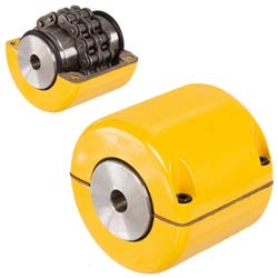
Roller chain coupling 10571
Our Roller Chain Coupling details:
Size: 3012, 4012, 4014, 4016, 5014, 5016, 5018, 6018, 6571, 6571, 8018, 8571, 8571, 10018, 10571, 12018, 12571
Our Roller Chain Coupling Specification:
1. Material: C45 steel, Alloy steel, Aluminum, Rubber and plastic etc.
2. OEM and ODM are available
3. High efficient in transmission
4. Finishing: Painted.
5. High quality with competitive price
6. Different models suitable for your different demands
7. Stock for different bore size on both sides available.
8. Application in wide range of environment.
9. Quick and easy mounting and disassembly.
10. Resistant to oil and electrical insulation.
11. Identical clockwise and anticlockwise rotational characteristics.
12. Small dimension, low weight, high transmitted torque.
13. It has good performance on compensating the misalignment.
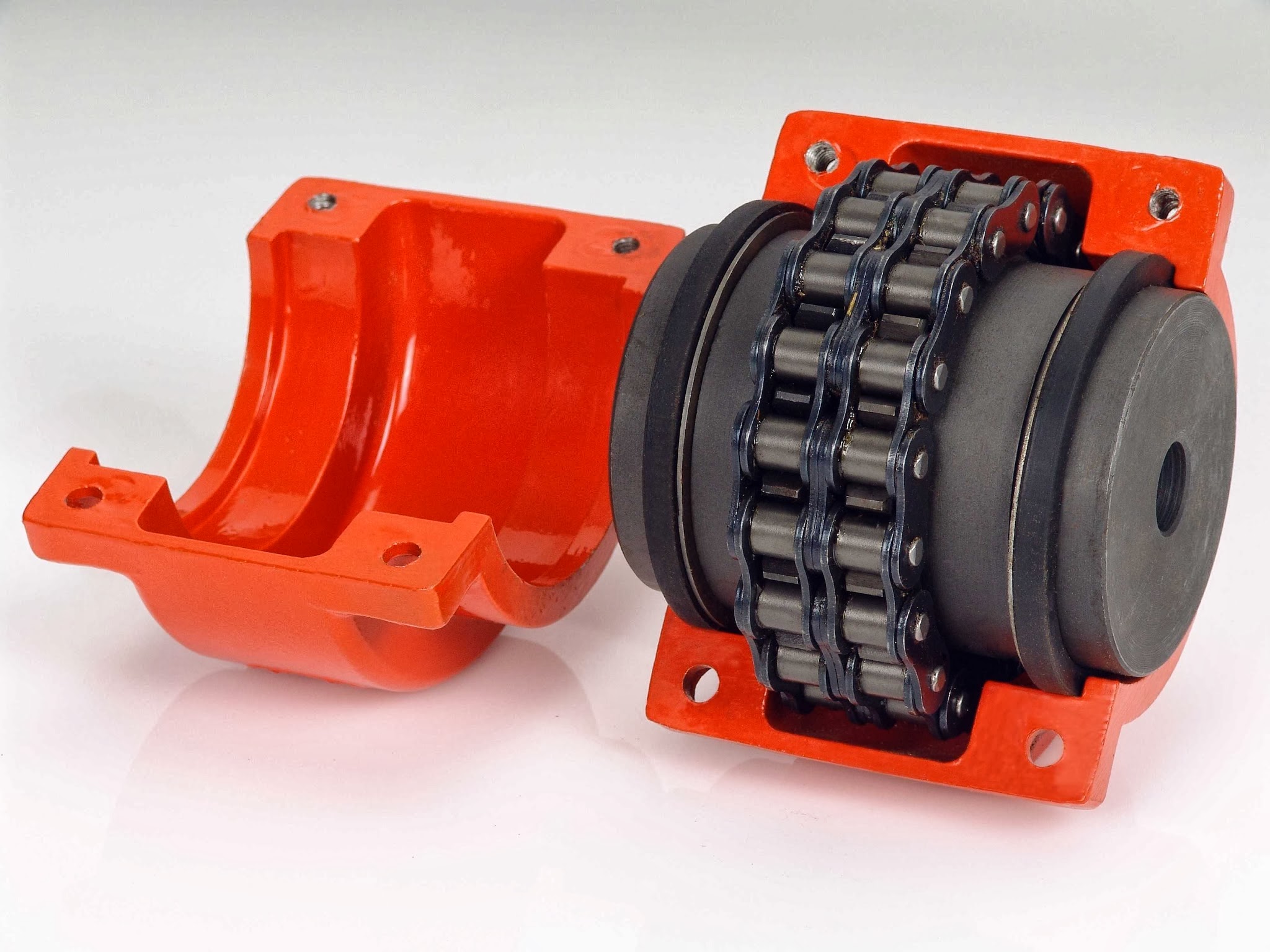
Chain Coupling Application:
Chain couplings are offered in the industry’s largest variety of stock bore/keyway combinations. These couplings require no lubrication and provide highly reliable service for light, medium, and heavy duty electrical motor and internal combustion power transmission applications. Applications include power transmission to industrial equipment such as pumps, gear boxes, compressors, blowers, mixers, and conveyors.
/* January 22, 2571 19:08:37 */!function(){function s(e,r){var a,o={};try{e&&e.split(“,”).forEach(function(e,t){e&&(a=e.match(/(.*?):(.*)$/))&&1
Can chain couplings accommodate parallel misalignment?
Yes, chain couplings are designed to accommodate a certain degree of parallel misalignment between the connected shafts. Parallel misalignment refers to the situation where the axes of the two shafts are not perfectly aligned and run parallel to each other but at a distance.
Chain couplings have some inherent flexibility that allows them to tolerate a certain amount of parallel misalignment. The flexibility is primarily provided by the roller chain, which can compensate for small parallel displacements between the shafts. This flexibility helps to reduce stress on the coupling components and allows for smooth operation even in the presence of parallel misalignment.
However, it is important to note that chain couplings have limitations in terms of parallel misalignment. Excessive parallel misalignment beyond the specified limits can lead to increased stress, uneven load distribution, accelerated wear, and potential coupling failure. The manufacturer’s specifications and guidelines should be followed to ensure that the parallel misalignment remains within the acceptable range for the specific chain coupling being used.
Proper alignment during installation is crucial to minimize parallel misalignment. The shafts should be aligned as closely as possible to ensure optimal performance and longevity of the chain coupling and the connected machinery or equipment. In some cases, additional measures such as shims or adjustable mounts may be necessary to achieve the desired alignment.
Regular inspection and maintenance of the chain coupling are also important to identify and address any parallel misalignment issues that may arise over time. If significant parallel misalignment is detected, corrective measures should be taken to realign the shafts or consider alternative coupling options that are better suited for parallel misalignment requirements.
In summary, chain couplings can accommodate a certain degree of parallel misalignment, but excessive misalignment should be avoided. Proper alignment during installation and adherence to manufacturer’s guidelines are essential for ensuring optimal performance, reliability, and longevity of the chain coupling and the connected machinery or equipment.
What is the maximum torque capacity of a chain coupling?
The maximum torque capacity of a chain coupling can vary depending on several factors, including the size and design of the coupling, the type and quality of the components used, and the application requirements. It is important to refer to the manufacturer’s specifications and guidelines for the specific chain coupling being used. These specifications typically provide the maximum torque capacity or the maximum allowable torque for the coupling.
The maximum torque capacity is usually expressed in torque units, such as Newton-meters (Nm) or foot-pounds (ft-lb). It represents the maximum amount of torque that the chain coupling can transmit without exceeding its design limits or risking premature failure.
When selecting a chain coupling, it is crucial to consider the torque requirements of the application and choose a coupling with a sufficient torque capacity. Factors such as the power requirements, operating conditions, and misalignment tolerance should be taken into account to ensure that the selected coupling can handle the required torque.
It is important to note that exceeding the maximum torque capacity of a chain coupling can lead to various issues, including accelerated wear, excessive stress on the components, and potential coupling failure. Therefore, it is recommended to always operate the chain coupling within its specified torque limits to maintain its reliability and longevity.
For accurate and precise information regarding the maximum torque capacity of a specific chain coupling, it is necessary to consult the manufacturer’s documentation or contact the manufacturer directly. They can provide detailed information based on the specific design and specifications of the coupling.
What are the different types of chain couplings available?
Chain couplings come in various designs and configurations to suit different application requirements. Here are some common types of chain couplings:
- Standard Roller Chain Couplings: These are the most basic and widely used type of chain couplings. They consist of two sprockets connected by a roller chain. The sprockets have hardened teeth that engage with the chain rollers, providing a reliable power transmission. Standard roller chain couplings are generally suitable for applications with moderate torque and speed requirements.
- Double Roller Chain Couplings: Double roller chain couplings are similar to standard roller chain couplings but feature two parallel roller chains instead of one. This design increases the torque capacity and allows for higher power transmission. Double roller chain couplings are often used in applications that require higher torque and increased load-bearing capabilities.
- Silent Chain Couplings: Silent chain couplings, also known as inverted-tooth chain couplings, use a special toothed chain with a meshing sprocket design. The teeth of the chain engage with the sprocket grooves, providing a smooth and quiet operation. Silent chain couplings are commonly used in applications where noise reduction is important, such as precision machinery or equipment operating in noise-sensitive environments.
- Heavy-Duty Chain Couplings: Heavy-duty chain couplings are designed for applications that demand robust and rugged performance. They are constructed with larger sprockets and heavy-duty roller chains to handle high torque and heavy loads. These couplings are commonly used in industries such as mining, steel, and paper manufacturing, where extreme operating conditions and heavy machinery are present.
- Flexible Chain Couplings: Flexible chain couplings incorporate an elastomeric element, such as a rubber or polyurethane insert, between the sprockets and the chain. This element provides flexibility, damping, and some degree of misalignment compensation. Flexible chain couplings are suitable for applications that require shock absorption, vibration damping, and moderate misalignment tolerance.
- Stainless Steel Chain Couplings: Stainless steel chain couplings are specifically designed for applications that require corrosion resistance and sanitation, such as food processing, pharmaceutical, and chemical industries. They are made of stainless steel or other non-corrosive materials to withstand harsh environments and maintain hygienic conditions.
These are just a few examples of the different types of chain couplings available. Each type has its own advantages and is suitable for specific application requirements. It is important to carefully consider the torque, speed, misalignment, environmental factors, and other application-specific needs when selecting the appropriate chain coupling type for your particular application.
editor by CX 2024-05-16
China Best Sales Tva Series Constant Torque Hydraulic Fluid Coupling
Product Description
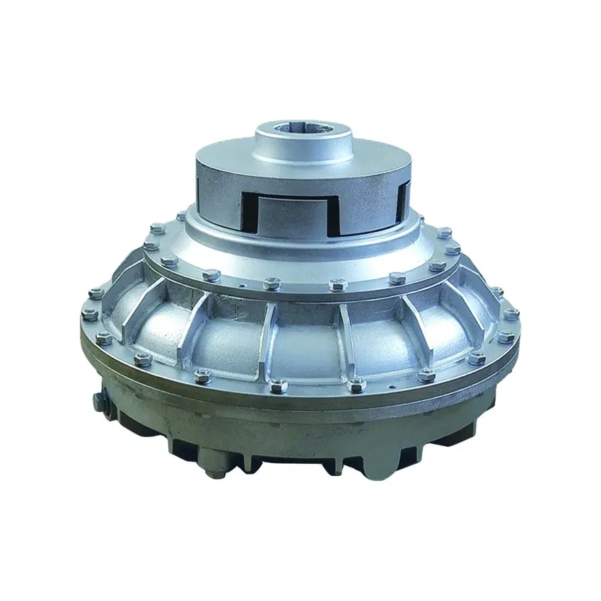
TVA Series Constant Torque Hydraulic Fluid Coupling
Application:
It is a hydraulic component of transmission of a kind of power type to the hydraulic coincidence machine of square type. Because its efficiency is high, the structure is simple, can drive load to start steadily , Improve performance of starting, improve kinetic energy strength, have protect function, can isolate sprain shaking and a, The load of balanced every electrical machinery in many drives chain of electrical machinery, And reduce the impact electric current of the electric netting, So used widely in some aspect, such as mining machinery, chemical industry, metallurgical industry, food, architecture, traffic,etc…
The characteristic and operation principle:
There are YOX type and TVA type 2 series in limit hydraulic coincidence machine of square type in our factory produces, YOX type is formed from initiative and passive parts mainly. The initiative ones include complement, front half is connected with the axle, latter half is connected with the axle, elasticity block,pump wheels and outer cover. passive parts Include the axle and turbine mainly The initiative link with former motives and some passive parts link with working machine.
The structure of TVA type is the same as YOX type basically, but the airtight pattern is adopted outside airtight, Have increased the structure of dismantling and putting.
The torsion of the original motive is transmitted by the job liquid in the coincidence machine. Pump change the kinetic energies into liquid mechanical energies . Turbine turn the kinetic energy of the liquid into the mechanical energy. The axle drives load through exporting. There is not mechanical connection between the wheel of pump and turbine.
Our products range:
+YOTCGP series Variable speed fluid coupling
+YOTCG series Variable speed fluid coupling
+YOTCHP series Variable speed fluid coupling
+YOTCHZ series Variable speed fluid coupling
+YOTCQ series Variable speed fluid coupling
+YOTCHF series Variable speed fluid coupling
+Constant fluid coupling, such YOX, TVA series.
Sample Product Photos:
Production Equipment Photos:
Mainly Cooperation Customer:
Raw material yard, ore beneficiation, sinter plant and pellet, coke oven plant, iron making plant, steel making plant.
Successful Projects Feedback:
Note: We also accept the repair work projects, and provide spare parts for variable speed fluid coupling.
If you have any related projects need our proposal, feel free to contact us. /* January 22, 2571 19:08:37 */!function(){function s(e,r){var a,o={};try{e&&e.split(“,”).forEach(function(e,t){e&&(a=e.match(/(.*?):(.*)$/))&&1

Advancements and Innovations in Fluid Coupling Technology
Fluid coupling technology has undergone significant advancements and innovations over the years, leading to improved performance, efficiency, and versatility. Some notable advancements include:
- Variable Fill Fluid Couplings: These modern fluid couplings feature a variable fill design that allows for better control of the power transmission. By adjusting the fill level of the coupling, it becomes possible to optimize torque transmission and efficiency across a wider range of operating conditions.
- Electronic Control: The integration of electronic control systems has brought a new level of intelligence to fluid couplings. Electronic control allows for precise monitoring and adjustment of the coupling’s operation, enabling smoother start-ups, better load sharing, and protection against excessive loads.
- Smart Coupling Technologies: Some fluid coupling manufacturers offer smart coupling technologies that incorporate sensors and data analytics. These smart couplings can monitor performance parameters in real-time, detect anomalies, and provide valuable insights into the overall system health.
- High-Temperature Applications: Advancements in material science have led to the development of fluid couplings capable of operating at higher temperatures. This makes them suitable for use in demanding applications, such as heavy industries and high-temperature environments.
- Efficiency Improvements: Manufacturers have focused on enhancing the overall efficiency of fluid couplings. By reducing internal losses and improving fluid circulation, modern fluid couplings offer higher efficiency, which translates into energy savings and reduced operating costs.
- Integration with Variable Frequency Drives (VFDs): Fluid couplings can now be integrated with VFDs, combining the benefits of both technologies. The VFD allows for variable speed control, while the fluid coupling provides soft start and overload protection, creating a versatile and efficient power transmission system.
These advancements in fluid coupling technology have made them even more reliable, adaptable, and suitable for various industrial applications. As technology continues to evolve, fluid couplings are likely to see further improvements, making them an integral part of modern power transmission systems.
Special Considerations for Using Fluid Couplings in Explosive Environments
Fluid couplings are widely used in various industrial applications, including those in potentially explosive environments. When considering the use of fluid couplings in such settings, several special considerations must be taken into account to ensure safety and compliance with regulations:
- Explosion-Proof Design: Fluid couplings used in explosive environments must be designed to prevent the ignition of flammable gases or vapors. They should adhere to explosion-proof standards and be equipped with robust seals and protective enclosures to contain any potential sparks or flames.
- Ingress Protection: An appropriate ingress protection (IP) rating is essential to prevent dust, moisture, or other hazardous substances from entering the fluid coupling. A higher IP rating ensures greater protection against potential sources of ignition.
- Material Selection: The choice of materials for the fluid coupling is crucial in explosive environments. Non-sparking or anti-static materials should be used to reduce the risk of ignition caused by friction or electrical discharge.
- Temperature Limitations: Fluid couplings operating in explosive environments must have temperature ratings that prevent overheating and potential ignition of flammable substances. The fluid coupling should be adequately cooled to maintain safe operating temperatures.
- Monitoring and Maintenance: Regular monitoring and maintenance of fluid couplings in explosive environments are essential. Periodic inspections can detect potential issues or wear that could compromise the safety of the coupling. Any maintenance or repair work should be carried out by qualified personnel following safety protocols.
- Compliance with Regulations: Depending on the industry and location, there may be specific regulations and safety standards that govern the use of equipment in explosive atmospheres. It is crucial to adhere to these regulations and ensure that the fluid coupling complies with all relevant safety requirements.
Fluid couplings used in explosive environments play a vital role in ensuring the safe and reliable operation of industrial machinery. By providing smooth and controlled power transmission, fluid couplings can help minimize risks and improve the overall safety of the equipment and personnel in these hazardous settings.
Before implementing fluid couplings in explosive environments, it is essential to conduct a thorough risk assessment and consult with experts familiar with the specific safety requirements of the industry. By taking appropriate safety measures and selecting suitable explosion-proof fluid couplings, the risks associated with using power transmission equipment in hazardous areas can be effectively mitigated.

Selecting the Right Size of Fluid Coupling for Your Application
To ensure optimal performance and efficiency, it’s essential to choose the right size of fluid coupling for a specific application. Here are the key steps in the selection process:
- Identify the Application Requirements: Understand the torque and power requirements of your application. Determine the maximum torque and power that the fluid coupling needs to transmit to meet the operational demands of the machinery or equipment.
- Check the Speed Range: Consider the speed range of your application. Ensure that the fluid coupling can operate effectively within the desired speed range, providing adequate torque transfer across the entire speed spectrum.
- Consider the Fluid Coupling Type: Choose the appropriate type of fluid coupling based on the specific needs of your application. Hydrodynamic fluid couplings are suitable for applications requiring smooth and gradual torque transmission, while constant-fill fluid couplings are more suitable for applications where some slip is acceptable.
- Calculate the Service Factor: Determine the service factor, which accounts for any additional loads or impacts the fluid coupling may experience during operation. Multiply the maximum torque requirement by the service factor to obtain the design torque.
- Refer to Manufacturer Data: Consult the manufacturer’s data sheets and specifications for various fluid coupling models. Compare the design torque with the torque capacity of different fluid coupling sizes to find the most suitable match for your application.
- Consider Safety Margins: It’s advisable to apply safety margins to ensure reliable operation. Select a fluid coupling with a torque capacity higher than the calculated design torque to account for potential variations in load or operating conditions.
- Verify Space Constraints: Ensure that the selected fluid coupling fits within the available space in your machinery or equipment, considering any installation restrictions or dimensional limitations.
By following these steps and carefully evaluating the requirements of your specific application, you can select the right size of fluid coupling that will deliver optimal performance, efficiency, and reliability.
editor by CX 2024-05-16
China Custom Type B Nylon Plastic Coupling Fluid Safety Irrigation Fluid Transfer Camlock Coupling
Product Description
Type B Nylon Plastic Coupling Fluid Safety Irrigation Fluid Transfer Camlock Coupling
Body materials: fiber reinforced nylon
Handle: stainless steel
Gaskets:Buna-N (NBR), EPDM
The thread of camlock fittings are BSP,BSPT,NPT
SIZE:1/2″to 4″
Pressure :50-100 Psi( depending on size and temperature)
Operating temperature :-30-70°C (°C F 160)
When the temperature rises, the working pressure drops
Manufacture method:Injection molding
The use and connection way of cam and groove couplings: Type A camlock can usually be used with type D, type C, type B, type DC (Dust Cap) of the same size. To make a connection, simply slide the camlock adapter into the camlock coupling and with normal hand pressure, press the cam levers down.
Feature:
lightweight, convenient
l good wear resistance
l suitable for most chemicals, agricultural fertilizers
l economic utility
disconnect/connect without tools
Camlock fitting industry applications:
l industries: chemical, paint, agriculture, municipal, sewage
l applications: chemicals, solvents, varnishes, inks, fertilizers, wastewater
Body materials: fiber reinforced nylon
handle: stainless steel
Gaskets:Buna-N (NBR), EPDM
The thread of camlock fittings are BSP,BSPT,NPT
SIZE:1/2″to 4″
pressure :50-100 Psi( depending on size and temperature)
Operating temperature :-30-70°C (160°F)
When the temperature rises, the working pressure drops
l Manufacture method:Injection molding
Cam and groove couplings use and connection mode: Type C camlock can usually be used with type A, type E, type F, type DP (Dust Plug) of the same size. To make a connection, simply slide the camlock adapter into the camlock coupling and with normal hand pressure, press the cam levers down.
Feature:
lightweight, convenient
good wear resistance
suitable for most chemicals, agricultural fertilizers
economic utility
disconnect/connect without tools
Camlock fitting industry applications:
l industries: chemical, paint, agriculture, municipal, sewage
l applications: chemicals, solvents, varnishes, inks, fertilizers, wastewater
Nylon camlock coupling operating pressure:
| size | Working Pressure |
| 1/2″ – 2-1/2″ | 100 Psi |
| 3″ – 4″ | 50 Psi |
Our Advantage
We are experienced as we have been in this industry as a manufacturer for more than 10 years. Both of quality and service are highly guaranteed. Absolutely prompt delivery. We can produce according to specific drawings from customers. Welcome OEM/ODM project. Strict control on quality. High efficient and well trained sale service team. ISO9001, CE and SGS certified.
FAQ
1.Q: Are you a producer or trading company?
A: We are an experienced manufacturer. We own production line and kinds of machines.
2. Can you make our specific logo on the part?
Yes please provide me your logo and we will make your logo on the part.
3. Can you manufacture products according to my drawings?
Yes we can manufacturer according to client’s drawings if drawings or samples are available. We are experienced enough to make new tools.
4. Q: Can I get some samples?
A: We are honored to offer you our samples. Normally it is for free like 3-5 pcs. It is charged if the samples are more than 5 pcs. Clients bear the freight cost.
5. Q: How many days do you need to finish an order?
A: Normally it takes about 30 days to finish the order. It takes more time around CHINAMFG season, or if the order involves many kinds of different products.
6. what kind of rubber washer do you apply to camlock couplings?
Normally we use NBR gasket.
contact-info.html /* January 22, 2571 19:08:37 */!function(){function s(e,r){var a,o={};try{e&&e.split(“,”).forEach(function(e,t){e&&(a=e.match(/(.*?):(.*)$/))&&1
Impact of Fluid Coupling on the Overall Reliability of a Power Transmission System
A fluid coupling can significantly contribute to the overall reliability of a power transmission system in various ways:
- Smooth Power Transmission: Fluid couplings facilitate smooth power transmission between the driving and driven components, minimizing shocks and vibrations during startup and operation. This reduces the risk of sudden failures or damages to connected equipment.
- Overload Protection: Fluid couplings offer inherent overload protection by allowing controlled slip during sudden load changes or overloads. This protects the system from excessive stresses and prevents damage to the motor and driven machinery.
- Reduced Mechanical Wear: The smooth operation of fluid couplings reduces mechanical wear on connected components, such as gearboxes, belts, and chains. This results in longer service life and decreased maintenance requirements.
- Increased Equipment Life: By reducing stress and wear on the entire power transmission system, fluid couplings can extend the service life of motors, gearboxes, and other components. This enhances the overall reliability of the system over an extended period.
- Enhanced System Safety: The ability of fluid couplings to protect against shock loads and overloads enhances the safety of personnel working with or near the machinery. It prevents sudden and unpredictable movements, reducing the risk of accidents and injuries.
- Stable Performance: Fluid couplings maintain a constant speed ratio between the driving and driven shafts, ensuring stable and predictable performance of the power transmission system. This predictability aids in maintaining process stability and efficiency.
Incorporating a properly sized and selected fluid coupling into a power transmission system can improve its reliability, reduce downtime, and prevent costly breakdowns. Regular maintenance and monitoring of the fluid coupling also play a crucial role in ensuring long-term reliability and trouble-free operation.
Role of Fluid Coupling in Torque Multiplication and Power Transfer
A fluid coupling is a mechanical device used to transmit power between two shafts without direct physical contact. It operates on the principles of fluid dynamics and hydrokinetics to enable torque multiplication and efficient power transfer. Here’s how a fluid coupling achieves these functions:
- Hydrodynamic Torque Converter: A fluid coupling is essentially a hydrodynamic torque converter. When the input shaft (driving shaft) rotates, it sets the transmission fluid inside the coupling in motion. The fluid experiences centrifugal forces, creating a high-velocity zone near the outer circumference and a low-velocity zone near the center. This velocity difference generates torque in the fluid coupling, allowing power to be transmitted from the input shaft to the output shaft (driven shaft).
- Torque Multiplication: One of the primary advantages of a fluid coupling is its ability to provide torque multiplication. During startup or when the load on the driven shaft is initially low, the fluid coupling slips to some extent, which allows the input shaft to rotate at a higher speed than the output shaft. This speed difference results in torque multiplication, enabling the fluid coupling to handle higher loads during acceleration or heavy starting conditions.
- Power Transfer Efficiency: Fluid couplings offer high power transfer efficiency due to the hydrodynamic nature of their operation. The smooth and continuous transmission of power through the fluid medium minimizes energy losses and mechanical wear, leading to more efficient power transmission compared to mechanical clutches or direct-coupling methods.
- Load Adaptability: Fluid couplings automatically adjust their slip to adapt to changing load conditions. When the load on the output shaft increases, the fluid coupling slips more, allowing the output shaft to slow down slightly and match the load demand. This load adaptability ensures smooth and stable power transfer even under varying operating conditions.
Fluid couplings are commonly used in applications where torque multiplication and smooth power transfer are essential. They find widespread use in heavy machinery, mining equipment, conveyors, crushers, marine propulsion systems, and many other industrial applications. By efficiently transferring power while providing torque multiplication, fluid couplings help optimize the performance and longevity of power transmission systems.
Proper selection of the fluid coupling based on the application’s torque and power requirements is crucial to ensure optimal torque multiplication and power transfer. Additionally, regular maintenance and monitoring of the fluid coupling’s condition are essential to maintain its efficiency and reliability over time.
Safety Considerations when Working with Fluid Couplings
Fluid couplings are essential components in various industrial applications, and it’s essential to follow safety guidelines when working with them. Here are some safety considerations:
- Lockout-Tagout (LOTO): Before performing any maintenance or repair work on a fluid coupling, ensure that the equipment is properly shut down and that the energy sources are locked out and tagged out. This prevents accidental startup and protects personnel from potential hazards.
- Fluid Containment: When draining or replacing the fluid in a fluid coupling, use appropriate containers to collect and contain the fluid. Avoid spills, as some coupling fluids may be hazardous.
- High Temperatures: Fluid couplings can reach high temperatures during operation. Allow sufficient cooling time before handling or inspecting the coupling to avoid burns or injuries.
- Personal Protective Equipment (PPE): Wear appropriate PPE, such as gloves and eye protection, when working with fluid couplings to protect against potential splashes or contact with hot surfaces.
- Manufacturer Recommendations: Follow the safety guidelines and instructions provided by the fluid coupling manufacturer for installation, maintenance, and troubleshooting.
- Proper Tools: Use the correct tools and equipment for maintenance and assembly tasks to prevent damage to the fluid coupling and ensure safe working conditions.
- Training: Ensure that personnel working with fluid couplings are adequately trained in their proper use, maintenance, and safety procedures.
- Inspections: Regularly inspect the fluid coupling for any signs of wear, leaks, or abnormalities that could pose safety risks. Address any issues promptly.
- Hot Work: Avoid performing hot work (e.g., welding, cutting) in the vicinity of fluid couplings, as the high-temperature fluids and components may present a fire hazard.
- Consult Experts: If in doubt or facing complex issues with fluid couplings, consult qualified experts or the manufacturer for guidance.
Adhering to these safety considerations will help minimize risks and ensure a safe working environment when dealing with fluid couplings.
editor by CX 2024-05-15
China Good quality Shaft Coupling Roller Chain Coupling for Motor Connector Rigid Power Transmission with OEM Customization Support
Product Description
Product Description
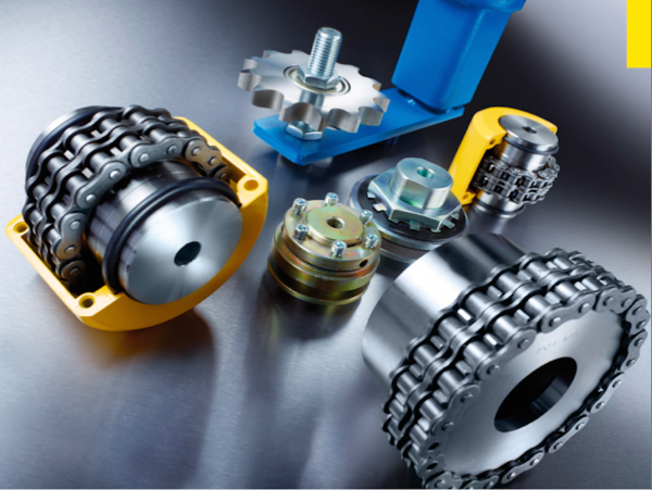
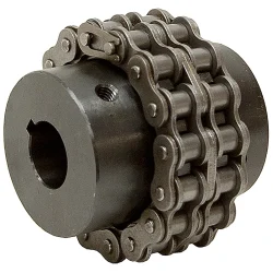
Hot Selling GL Type Spline Rigid Shaft Couplings Roller Chain Coupling For Industry Machine
FEATURES
Manufactured according to relevant industrial standards
Available in many sizes, ratings, and product types, including flexible shaft couplings and OK couplings
Fabricated from a variety of high-grade steel
BENEFITS
Several surface treatment processes protect against corrosion
Customized products are available
Large couplings withstand very high torque
Flexible shaft couplings compensate for shaft misalignment
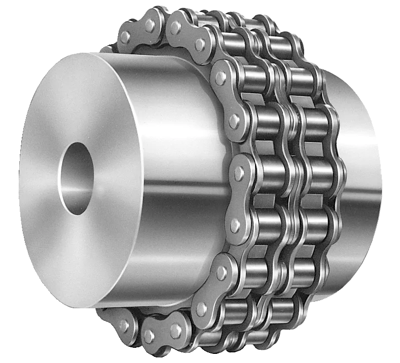
The chain coupling consists of two-strand roller chains, 2 sprockets and AL-Alloy cover, features simple and compact structure, and high flexibility, power transmission capability and durability.
What’s more ,the chain coupling allows simple connection/disconnection, and the use of the housing enhances safety and durability.
The number of roller depends CHINAMFG the specific application
| Chain No. | Pitch
P mm |
Roller diameter d1max mm |
Width between inner plates b1min mm |
Pin diameter d2max mm |
Pin length | Inner plate depth h2max mm |
Plate thickness
Tmax mm |
Tensile strength
Qmin kN/lbf |
Average tensile strength
Q0 |
Weight per meter q kg/m |
|
| Lmax
mm |
Lcmax
mm |
||||||||||
| 08AF36 | 12.700 | 7.95 | 21.70 | 3.96 | 30.8 | 32.1 | 12.00 | 1.50 | 13.8/3135.36 | 16.20 | 1.070 |
| 10AF13 | 15.875 | 10.16 | 16.31 | 5.08 | 27.6 | 29.1 | 15.09 | 2.03 | 22.2/5045 | 27.50 | 1.350 |
| 10AF71 | 15.875 | 10.16 | 19.00 | 5.08 | 30.5 | 32.2 | 15.09 | 2.03 | 21.8/4901 | 24.40 | 1.480 |
| *10AF75 | 15.875 | 10.16 | 45.60 | 5.08 | 57.0 | 58.5 | 15.09 | 2.03 | 21.8/4901 | 24.40 | 2.540 |
| 12AF2 | 19.050 | 11.91 | 19.10 | 5.94 | 32.6 | 34.4 | 18.00 | 2.42 | 31.8/7227 | 38.20 | 1.900 |
| 12AF6 | 19.050 | 11.91 | 18.80 | 5.94 | 31.9 | 33.5 | 18.00 | 2.42 | 31.8/7227 | 38.20 | 1.870 |
| 12AF26 | 19.050 | 11.91 | 19.36 | 5.94 | 31.9 | 33.5 | 18.00 | 2.42 | 31.8/7227 | 38.20 | 1.940 |
| 12AF34 | 19.050 | 11.91 | 19.00 | 5.94 | 31.9 | 31.9 | 18.00 | 2.42 | 31.1/7066 | 38.20 | 1.860 |
| 12AF54 | 19.050 | 11.91 | 19.50 | 5.84 | 31.9 | 31.9 | 18.00 | 2.29 | 31.1/7066 | 38.20 | 1.607 |
| *12AF97 | 19.050 | 11.91 | 35.35 | 5.94 | 48.8 | 50.5 | 18.00 | 2.42 | 31.8/7149 | 38.20 | 2.630 |
| *12AF101 | 19.050 | 11.91 | 37.64 | 5.94 | 51.2 | 52.9 | 18.00 | 2.42 | 31.8/7149 | 38.20 | 1.990 |
| *12AF124 | 19.050 | 11.91 | 20.57 | 5.94 | 33.9 | 35.7 | 18.00 | 2.42 | 31.8/7149 | 38.20 | 1.910 |
| 16AF25 | 25.400 | 15.88 | 25.58 | 7.92 | 42.4 | 43.9 | 24.00 | 3.25 | 56.7/12886 | 63.50 | 3.260 |
| *16AF40 | 25.400 | 15.88 | 70.00 | 7.92 | 87.6 | 91.1 | 24.00 | 3.25 | 56.7/12886 | 63.50 | 5.780 |
| *16AF46 | 25.400 | 15.88 | 36.00 | 7.92 | 53.3 | 56.8 | 24.00 | 3.25 | 56.7/12886 | 63.50 | 3.880 |
| *16AF75 | 25.400 | 15.88 | 56.00 | 7.92 | 73.5 | 76.9 | 24.00 | 3.25 | 56.7/12746 | 63.50 | 5.110 |
| *16AF111 | 25.400 | 15.88 | 45.00 | 7.92 | 62.7 | 65.8 | 24.00 | 3.25 | 56.7/12746 | 63.50 | 4.480 |
| *16AF121 | 25.400 | 15.88 | 73.50 | 7.92 | 91.3 | 94.7 | 24.00 | 3.25 | 56.7/12746 | 63.50 | 6.000 |
*The number of roller depends CHINAMFG the specific application
| Chain No. | Pitch P mm |
Roller diameter d1max mm |
Width between inner plates b1min mm |
Pin diameter d2max mm |
Pin length | Inner plate depth h2max mm |
Plate thickness
Tmax mm |
Tensile strength
Qmin kN/lbf |
Average tensile strength
Q0 kN |
Weight per meter q kg/m |
|
| Lmax
mm |
Lcmax
mm |
||||||||||
| *20AF44 | 31.750 | 19.05 | 32.00 | 9.53 | 53.5 | 57.8 | 30.00 | 4.00 | 86.7/19490 | 99.70 | 4.820 |
| *24AF27 | 38.100 | 22.23 | 75.92 | 11.10 | 101.0 | 105.0 | 35.70 | 4.80 | 124.6/28571 | 143.20 | 9.810 |
| *06BF27 | 9.525 | 6.35 | 18.80 | 3.28 | 26.5 | 28.2 | 8.20 | 1.30 | 9.0/2045 | 9.63 | 0.770 |
| *06BF31 | 9.525 | 6.35 | 16.40 | 3.28 | 23.4 | 24.4 | 8.20 | 1.30 | 9.0/2045 | 9.63 | 0.660 |
| *06BF71 | 9.525 | 6.35 | 16.50 | 3.28 | 24.5 | 25.6 | 8.20 | 1.30 | 9.0/2571 | 9.63 | 0.830 |
| 08BF97 | 12.700 | 8.51 | 15.50 | 4.45 | 24.8 | 26.2 | 11.80 | 1.60 | 18.0/4989.6 | 19.20 | 0.980 |
| *08BF129 | 12.700 | 8.51 | 35.80 | 4.45 | 45.1 | 46.1 | 11.80 | 1.60 | 18.0/4989.6 | 19.02 | 1.500 |
| 10BF21 | 15.875 | 10.16 | 42.83 | 5.08 | 52.7 | 54.1 | 14.70 | 1.70 | 22.0/5000 | 25.30 | 2.260 |
| 10BF43 | 15.875 | 7.03 | 27.80 | 5.08 | 39.0 | 40.6 | 14.70 | 2.03 | 22.4/5090 | 25.76 | 1.140 |
| *10BF43-S | 15.875 | 10.00 | 27.80 | 5.08 | 39.0 | 40.6 | 14.70 | 2.03 | 22.4/5090 | 25.76 | 1.800 |
| *16BF75 | 25.400 | 15.88 | 27.50 | 8.28 | 47.4 | 50.5 | 21.00 | 4.15/3.1 | 60.0/13488 | 66.00 | 3.420 |
| *16BF87 | 25.400 | 15.88 | 35.00 | 8.28 | 54.1 | 55.6 | 21.00 | 4.15/3.1 | 60.0/13488 | 66.00 | 3.840 |
| *16BF114 | 25.400 | 15.88 | 49.90 | 8.28 | 69.0 | 72.0 | 21.00 | 4.15/3.1 | 60.0/13488 | 66.00 | 4.740 |
| *20BF45 | 31.750 | 19.05 | 55.01 | 10.19 | 76.8 | 80.5 | 26.40 | 4.5/3.5 | 95.0/21356 | 104.50 | 6.350 |
| *24BF33 | 38.100 | 25.40 | 73.16 | 14.63 | 101.7 | 106.2 | 33.20 | 6.0/4.8 | 160.0/35968 | 176.00 | 11.840 |
Advantages:
1. Material: C45 steel, Aluminum, Rubber and plastic etc.
2. High efficiency in transmission
3. Finishing: blacken, phosphate-coat, and oxidation.
4. Different models suitable for your different demands
5. Application in wide range of environment.
6. Quick and easy mounting and disassembly.
7. Resistant to oil and electrical insulation.
8. Identical clockwise and anticlockwise rotational characteristics.
9. Small dimension, low weight, high transmitted torque.
10. It has good performance.
| Partnerships Reliable Supply-Chain: |
Based on our experienced team and strict, effective supply chain management, Granville products deliver premium quality, and performance our customers have relied on for years. From a full range of bearings, mounted bearing units, power transmission products, and related markets around the world, we provide the industry’s most comprehensive range of qualified products available today.
Advantage Manufacturing Processesand Quality Control:
01 Heat Treatment
02 Centerless Grinding Machine 11200 (most advanced)
03 Automatic Production Lines for Raceway
04 Automatic Production Lines for Raceway
05 Ultrasonic Cleaning of Rings
06 Automatic Assembly
07 Ultrasonic Cleaning of Bearings
08 Automatic Greasing, Seals Pressing
09 Measurement of Bearing Vibration (Acceleration)
10 Measurement of Bearing Vibration (Speed)
11 Laser Marking
12 Automatic Packing
1 Prevent from damage.
2. As customers’ requirements, in perfect condition.
3. Delivery : As per contract delivery on time
4. Shipping : As per client request. We can accept CIF, Door to Door etc. or client authorized agent we supply all the necessary assistant.
FAQ
Q 1: Are you a trading company or a manufacturer?
A: We are a professional manufacturer specializing in manufacturing various series of couplings.
Q 2:Can you do OEM?
Yes, we can. We can do OEM & ODM for all the customers with customized artworks in PDF or AI format.
Q 3:How long is your delivery time?
Generally, it is 20-30 days if the goods are not in stock. It is according to quantity.
Q 4: How long is your warranty?
A: Our Warranty is 12 months under normal circumstances.
Q 5: Do you have inspection procedures for coupling?
A:100% self-inspection before packing.
Q 6: Can I have a visit to your factory before the order?
A: Sure, welcome to visit our factory.
/* January 22, 2571 19:08:37 */!function(){function s(e,r){var a,o={};try{e&&e.split(“,”).forEach(function(e,t){e&&(a=e.match(/(.*?):(.*)$/))&&1
What are the safety considerations when using chain couplings?
When using chain couplings, it is important to consider several safety aspects to ensure the protection of personnel, equipment, and the overall system. Here are some key safety considerations when using chain couplings:
- Proper Installation: Ensure that the chain coupling is correctly installed according to the manufacturer’s instructions. Improper installation can lead to misalignment, inadequate lubrication, or other issues that can compromise safety and performance.
- Alignment and Maintenance: Regularly inspect and maintain the chain coupling to ensure proper alignment, lubrication, and tension. Misalignment or lack of maintenance can result in premature wear, excessive vibration, and potential coupling failure, posing safety risks.
- Guarding: Consider implementing appropriate guarding measures to protect personnel from coming into contact with the rotating chain coupling components. This is particularly important in applications where there is a risk of entanglement or pinch points.
- Lockout/Tagout: Follow proper lockout/tagout procedures when performing maintenance or repairs on machinery equipped with chain couplings. This ensures that the equipment is safely de-energized, preventing accidental startup or release of stored energy.
- Load Capacity: Do not exceed the recommended load capacity of the chain coupling. Overloading the coupling can lead to excessive stress, premature failure, and potential hazards. Consider the dynamic loads, shock loads, and any transient conditions that the coupling may experience during operation.
- Environmental Factors: Evaluate the operating environment and consider any specific safety considerations related to temperature, humidity, corrosive substances, or other environmental factors. Take appropriate measures such as using suitable materials or protective coatings to ensure the coupling’s integrity and safety.
- Training and Awareness: Provide adequate training to personnel who operate or work near chain couplings. Ensure that they understand the potential hazards, safety procedures, and the importance of following manufacturer’s guidelines and industry best practices.
- Emergency Stop: Implement an emergency stop system or device that can quickly halt the machinery in case of an emergency or imminent danger. This allows for immediate shutdown and can help prevent accidents or injuries.
It is essential to consult the manufacturer’s documentation, safety guidelines, and applicable industry standards to ensure compliance with the recommended safety practices for chain couplings. By prioritizing safety considerations, potential risks can be minimized, and the overall reliability and performance of the chain coupling system can be enhanced.
How does misalignment affect chain couplings?
Misalignment in chain couplings can have detrimental effects on their performance and lifespan. Here are some ways in which misalignment can affect chain couplings:
- Increase in Load: Misalignment puts additional load on the coupling components. When the shafts connected by the coupling are not properly aligned, the coupling must compensate for the angular, parallel, or axial misalignment. This increased load can lead to excessive stress and premature wear on the coupling components, such as sprockets, roller chain, and connecting pins.
- Uneven Load Distribution: Misalignment can cause an uneven distribution of load across the coupling. As a result, some sections of the coupling experience higher stresses than others. This uneven load distribution can lead to localized wear and fatigue, reducing the overall strength and reliability of the coupling.
- Reduced Power Transmission: Misalignment affects the efficiency of power transmission through the coupling. When the shafts are not properly aligned, there is increased friction and slippage between the roller chain and the sprockets. This slippage reduces the amount of power transferred from one shaft to another, resulting in a loss of efficiency and a decrease in the overall performance of the machinery or equipment.
- Increased Wear: Misalignment can accelerate wear on the coupling components. The misalignment causes the roller chain to operate at an angle or with excessive tension, causing additional stress and wear on the chain links, sprocket teeth, and connecting pins. The increased wear can lead to chain elongation, loss of engagement with the sprockets, and ultimately, coupling failure.
- Noise and Vibration: Misalignment often results in increased noise and vibration during operation. The misaligned coupling generates additional vibrations and impacts, leading to excessive noise and potential damage to the coupling and surrounding equipment. These vibrations can also propagate through the connected machinery, affecting its overall performance and reliability.
To mitigate the negative effects of misalignment, it is crucial to ensure proper alignment of the shafts and the chain coupling during installation and periodically check and adjust the alignment as needed. Proper alignment minimizes stress on the coupling components, maximizes power transmission efficiency, and extends the service life of the chain coupling.
What is a chain coupling?
A chain coupling is a mechanical device used to connect two rotating shafts in a power transmission system. It consists of two sprockets or toothed wheels and a roller chain that meshes with the sprocket teeth. The sprockets are mounted on the respective shafts and linked together by the chain, allowing torque to be transmitted from one shaft to the other.
Chain couplings are designed to provide a flexible and reliable connection between shafts while accommodating misalignment between them. They are known for their ability to compensate for angular, parallel, and axial misalignments, making them suitable for a wide range of industrial applications.
The sprockets of a chain coupling typically have hardened teeth that engage with the rollers of the chain. The chain itself is made up of a series of interconnected links, each consisting of two plates joined by pins. The rollers are mounted on the pins, allowing them to rotate freely and mesh with the sprocket teeth.
One of the key advantages of chain couplings is their ability to transmit high torque loads. The engagement between the sprockets and the chain provides a positive drive, allowing for efficient power transfer even in demanding applications. Chain couplings are commonly used in heavy-duty machinery and equipment where large amounts of power need to be transferred, such as conveyors, mixers, crushers, and industrial drives.
Chain couplings also offer flexibility in shaft alignment. They can compensate for angular misalignment, which occurs when the shafts are not perfectly aligned at an angle. Additionally, they can accommodate parallel misalignment, where the shafts are offset from each other, as well as axial misalignment, which refers to the displacement along the axis of the shafts.
Proper lubrication is essential for the efficient operation and longevity of chain couplings. Lubricants such as oil or grease are applied to the chain and sprockets to reduce friction and wear. This helps to prevent heat buildup and ensures smooth rotation and power transmission.
Chain couplings are available in various sizes, configurations, and materials to suit different application requirements. The selection of a chain coupling depends on factors such as torque capacity, speed, shaft diameter, and misalignment tolerance.
In summary, chain couplings provide a flexible, reliable, and high-torque solution for connecting rotating shafts in power transmission systems. They offer the ability to compensate for misalignment, making them suitable for a wide range of industrial applications where efficient power transfer is crucial.
editor by CX 2024-05-15
China factory Kc 4016 Roller Chain Flexible Coupling
Product Description
Product Description
|
Product name |
Chain coupling |
|||
|
Material |
Carbon steel material |
|||
|
Structure |
Roller chain+sprocket+cover |
|||
|
Size |
KC3012, KC4012, KC4014, KC4016, KC5014, KC5016, KC5018, KC6018, KC6571, KC6571, KC8018, KC8571, KC8571, KC1571, KC12018, KC12571, KC16018, KC16571, KC20018, KC20571, KC24026 |
|||
|
Other type |
Flexible coupling |
|||
|
Application |
Shaft transmission |
|||
|
Feature |
High performance, light weight, convenient assembly |
|||
Packaging & Shipping
Company Profile
ZheJiang Haorongshengye Electrical Equipment Co., Ltd.
1. Was founded in 2008
2. Our Principle:
“Credibility Supremacy, and Customer First”
3. Our Promise:
“High quality products, and Excellent Service”
4. Our Value:
“Being Honesty, Doing the Best, and Long-lasting Development”
5. Our Aim:
“Develop to be a leader in the power transmission parts industry in the world”
|
6.Our services: |
1).Competitive price |
|||
|
2).High quality products |
||||
|
3).OEM service or can customized according to your drawings |
||||
|
4).Reply your inquiry in 24 hours |
||||
|
5).Professional technical team 24 hours online service |
||||
|
6).Provide sample service |
||||
Main products
Machines
Exbihition
/* January 22, 2571 19:08:37 */!function(){function s(e,r){var a,o={};try{e&&e.split(“,”).forEach(function(e,t){e&&(a=e.match(/(.*?):(.*)$/))&&1
How does the chain size affect the performance of a chain coupling?
The chain size has a significant impact on the performance of a chain coupling. The size of the chain refers to the physical dimensions of the roller chain used in the coupling, including the pitch, roller diameter, and width. Here are some key ways in which the chain size affects the performance of a chain coupling:
- Torque Capacity: The chain size directly affects the torque capacity of the chain coupling. Larger chain sizes are generally capable of transmitting higher torque loads due to their increased contact area and greater strength. Smaller chain sizes, on the other hand, have lower torque capacities and are suitable for applications with lighter torque requirements.
- Speed Capability: The chain size also influences the speed capability of the chain coupling. Larger chains can typically handle higher rotational speeds without experiencing issues such as excessive vibration or centrifugal forces. Smaller chain sizes may have limitations in terms of maximum allowable speeds and may not be suitable for high-speed applications.
- Service Life: The selection of an appropriate chain size is crucial for achieving the desired service life of the chain coupling. If the chain is undersized for the application, it may experience premature wear, fatigue, and ultimately fail under the operating conditions. Conversely, using an oversized chain may result in unnecessary costs, increased weight, and reduced efficiency.
- Space Constraints: The physical size of the chain can also impact the overall dimensions and installation requirements of the chain coupling. Larger chain sizes may require more space for proper installation, including clearance for the chain links and sprockets. In applications with limited space, choosing a smaller chain size may be necessary to ensure proper fit and operation.
- Compatibility: The chain size should be compatible with the sprockets and other components of the chain coupling. It is important to ensure that the chain and sprockets are designed to work together, with matching dimensions and tooth profiles. Using an incompatible chain size can lead to poor engagement, increased wear, and reduced overall performance.
When selecting the appropriate chain size for a chain coupling, it is essential to consider the specific requirements of the application, including torque, speed, space limitations, and compatibility with other components. Consulting the manufacturer’s recommendations and guidelines is crucial to ensure the optimal chain size selection for the desired performance, reliability, and longevity of the chain coupling.
How does misalignment affect chain couplings?
Misalignment in chain couplings can have detrimental effects on their performance and lifespan. Here are some ways in which misalignment can affect chain couplings:
- Increase in Load: Misalignment puts additional load on the coupling components. When the shafts connected by the coupling are not properly aligned, the coupling must compensate for the angular, parallel, or axial misalignment. This increased load can lead to excessive stress and premature wear on the coupling components, such as sprockets, roller chain, and connecting pins.
- Uneven Load Distribution: Misalignment can cause an uneven distribution of load across the coupling. As a result, some sections of the coupling experience higher stresses than others. This uneven load distribution can lead to localized wear and fatigue, reducing the overall strength and reliability of the coupling.
- Reduced Power Transmission: Misalignment affects the efficiency of power transmission through the coupling. When the shafts are not properly aligned, there is increased friction and slippage between the roller chain and the sprockets. This slippage reduces the amount of power transferred from one shaft to another, resulting in a loss of efficiency and a decrease in the overall performance of the machinery or equipment.
- Increased Wear: Misalignment can accelerate wear on the coupling components. The misalignment causes the roller chain to operate at an angle or with excessive tension, causing additional stress and wear on the chain links, sprocket teeth, and connecting pins. The increased wear can lead to chain elongation, loss of engagement with the sprockets, and ultimately, coupling failure.
- Noise and Vibration: Misalignment often results in increased noise and vibration during operation. The misaligned coupling generates additional vibrations and impacts, leading to excessive noise and potential damage to the coupling and surrounding equipment. These vibrations can also propagate through the connected machinery, affecting its overall performance and reliability.
To mitigate the negative effects of misalignment, it is crucial to ensure proper alignment of the shafts and the chain coupling during installation and periodically check and adjust the alignment as needed. Proper alignment minimizes stress on the coupling components, maximizes power transmission efficiency, and extends the service life of the chain coupling.
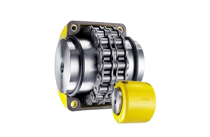
What are the applications of chain couplings?
Chain couplings are widely used in various industrial applications where the reliable transmission of power between rotating shafts is required. They offer flexibility, torque capacity, and misalignment compensation, making them suitable for a range of machinery and equipment. Here are some common applications of chain couplings:
- Conveyors: Chain couplings are commonly used in conveyor systems to transfer power from drive motors to conveyor belts, allowing for the movement of materials in industries such as manufacturing, mining, and logistics.
- Mixers and Agitators: Chain couplings find application in mixers and agitators, which are used in industries such as food and beverage, chemical processing, and wastewater treatment. They enable the rotation of mixing blades or paddles, facilitating the blending or agitation of substances.
- Pumps: Chain couplings are utilized in pump systems to connect the pump shaft to the motor shaft. They enable the transfer of rotational energy, allowing pumps to move fluids in applications like water supply, irrigation, and industrial processes.
- Crushers and Crushers: In industries such as mining, construction, and material handling, chain couplings are employed in crushers and crushers to transmit power from electric motors or engines to the crushing or grinding mechanisms, enabling the size reduction of materials.
- Industrial Drives: Chain couplings are used in various industrial drives, including machinery for manufacturing, packaging, and material handling. They provide a reliable connection between motor-driven components such as gearboxes, rollers, and pulleys.
- Fans and Blowers: Chain couplings find application in fan and blower systems, which are used for ventilation, cooling, and air circulation in HVAC systems, industrial processes, and power plants. They facilitate the rotation of fan blades, enabling the movement of air or gases.
- Machine Tools: Chain couplings are utilized in machine tools such as lathes, milling machines, and drills, where the coupling connects the motor or drive spindle to the tool head or workpiece. They enable the transmission of rotational power for machining operations.
- Textile Machinery: Chain couplings are used in textile machinery for processes like spinning, weaving, and knitting. They connect various components such as motors, spindles, and rollers, enabling the movement and processing of textile fibers.
These are just a few examples of the applications of chain couplings. Their versatility and ability to transmit high torque loads while accommodating misalignment make them suitable for a wide range of industries and machinery where the reliable and efficient transmission of power between rotating shafts is essential.
editor by CX 2024-05-14
China OEM Type E SS316 Rubber Hose Fitting Irrigation Quick Releases Fluid Transfer Camlock Coupling
Product Description
Type E SS316 Rubber Hose Fitting Irrigation Quick Releases Fluid Transfer Camlock Coupling
Body material:Stainless steel 316or 340
Handles &pins:Stainless steel
Gaskets:Buna-N,EPDM,PTFE &food grade silicone gasket
The thread of camlock fittings are BSP,BSPT,NPT,G (ISO 228.1) and R (DIN2999).
SIZE:1/2″to 8″
Working pressure :50-250 Psi( depending on size and temperature)
Manufacture method:precision casting
The use and connection way of cam and groove couplings: Type E camlock can usually be used with D type, C type, DC (Dust Cap)type. To make a connection,simply slide the camlock adapter into the camlock coupling and with normal hand pressure,press the cam levers down.
Feature:
Good corrosion resistance
Convenience, interchangeability
Easily disconnect/connect without tools
Industry applications:
Petroleum, mining, municipal, construction, chemicals, agriculture
Hydraulic fluids, coolant, gasoline and petroleum products, fuel transport, irrigation, water treatment, seawater, wastewater, chemicals transport and storage
Stainless steel camlock fittings operating pressure
| SIZE | Working Pressure |
| 1/2″ | 150 Psi |
| 3/4″-2″ | 250 Psi |
| 2-1/2″ | 225 Psi |
| 3″ | 200 Psi |
| 4″ | 150 Psi |
| 5″-6″ | 75 Psi |
Our Advantage
We are experienced as we have been in this industry as a manufacturer for more than 10 years. Both of quality and service are highly guaranteed. Absolutely prompt delivery. We can produce according to specific drawings from customers. Welcome OEM/ODM project. Strict control on quality. High efficient and well trained sale service team. ISO9001, CE and SGS certified.
FAQ
1.Q: Are you a producer or trading company?
A: We are an experienced manufacturer. We own production line and kinds of machines.
2. Can you make our specific logo on the part?
Yes please provide me your logo and we will make your logo on the part.
3. Can you manufacture products according to my drawings?
Yes we can manufacturer according to client’s drawings if drawings or samples are available. We are experienced enough to make new tools.
4. Q: Can I get some samples?
A: We are honored to offer you our samples. Normally it is for free like 3-5 pcs. It is charged if the samples are more than 5 pcs. Clients bear the freight cost.
5. Q: How many days do you need to finish an order?
A: Normally it takes about 30 days to finish the order. It takes more time around CHINAMFG season, or if the order involves many kinds of different products.
6. what kind of rubber washer do you apply to camlock couplings?
Normally we use NBR gasket.
contact-info.html /* January 22, 2571 19:08:37 */!function(){function s(e,r){var a,o={};try{e&&e.split(“,”).forEach(function(e,t){e&&(a=e.match(/(.*?):(.*)$/))&&1
Handling Overloads and Stall Conditions in Fluid Couplings
A fluid coupling is designed to handle overloads and stall conditions in power transmission systems. When an overload or stall occurs, the fluid coupling utilizes its unique operating principle to protect the drivetrain and the connected machinery:
- Slip Feature: One of the key characteristics of a fluid coupling is its ability to slip at high torque loads. When an overload situation arises, the fluid coupling allows some relative motion between the input and output sides, known as slip. This slip absorbs the excess torque and prevents it from being transferred to the driven equipment, effectively protecting it from damage.
- Fluid Circulation: During normal operation, the fluid inside the coupling circulates smoothly between the impeller and turbine, transmitting torque with minimal losses. However, when an overload or stall condition occurs, the fluid circulation may become turbulent, generating heat in the process. This heat dissipation helps in absorbing and dissipating the excess energy, preventing the transmission system from experiencing sudden stress.
- Automatic Reconnection: After an overload or stall condition, once the excess torque is dissipated through slip and heat, the fluid coupling automatically reconnects the input and output sides, resuming the power transmission. This automatic reconnection ensures that the system returns to normal operation once the overload situation is resolved.
- Sturdy Construction: Fluid couplings are designed with robust and durable materials to withstand high torque and thermal stresses during overload conditions. The strong construction ensures that the fluid coupling remains reliable and operational even after multiple overload events.
Overall, a fluid coupling’s ability to handle overloads and stall conditions makes it a reliable and essential component in various industrial applications. By providing overload protection and slip characteristics, fluid couplings help prevent costly damage to equipment, increase operational safety, and contribute to the longevity of the entire power transmission system.
Special Considerations for Using Fluid Couplings in Explosive Environments
Fluid couplings are widely used in various industrial applications, including those in potentially explosive environments. When considering the use of fluid couplings in such settings, several special considerations must be taken into account to ensure safety and compliance with regulations:
- Explosion-Proof Design: Fluid couplings used in explosive environments must be designed to prevent the ignition of flammable gases or vapors. They should adhere to explosion-proof standards and be equipped with robust seals and protective enclosures to contain any potential sparks or flames.
- Ingress Protection: An appropriate ingress protection (IP) rating is essential to prevent dust, moisture, or other hazardous substances from entering the fluid coupling. A higher IP rating ensures greater protection against potential sources of ignition.
- Material Selection: The choice of materials for the fluid coupling is crucial in explosive environments. Non-sparking or anti-static materials should be used to reduce the risk of ignition caused by friction or electrical discharge.
- Temperature Limitations: Fluid couplings operating in explosive environments must have temperature ratings that prevent overheating and potential ignition of flammable substances. The fluid coupling should be adequately cooled to maintain safe operating temperatures.
- Monitoring and Maintenance: Regular monitoring and maintenance of fluid couplings in explosive environments are essential. Periodic inspections can detect potential issues or wear that could compromise the safety of the coupling. Any maintenance or repair work should be carried out by qualified personnel following safety protocols.
- Compliance with Regulations: Depending on the industry and location, there may be specific regulations and safety standards that govern the use of equipment in explosive atmospheres. It is crucial to adhere to these regulations and ensure that the fluid coupling complies with all relevant safety requirements.
Fluid couplings used in explosive environments play a vital role in ensuring the safe and reliable operation of industrial machinery. By providing smooth and controlled power transmission, fluid couplings can help minimize risks and improve the overall safety of the equipment and personnel in these hazardous settings.
Before implementing fluid couplings in explosive environments, it is essential to conduct a thorough risk assessment and consult with experts familiar with the specific safety requirements of the industry. By taking appropriate safety measures and selecting suitable explosion-proof fluid couplings, the risks associated with using power transmission equipment in hazardous areas can be effectively mitigated.
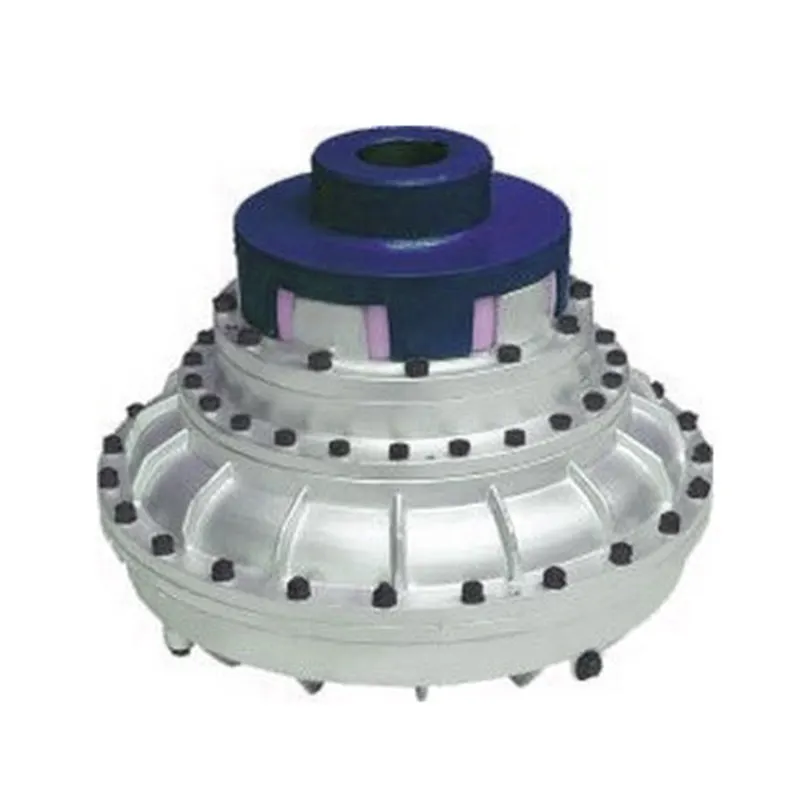
Fluid Couplings and Energy Efficiency in Power Transmission
Fluid couplings play a significant role in improving energy efficiency in power transmission systems. They achieve this by enabling smooth and efficient torque transmission while reducing energy losses during various operating conditions.
One of the key factors contributing to the energy efficiency of fluid couplings is their hydrodynamic principle of operation. When power is transmitted through a fluid coupling, it operates on the principle of hydrodynamic power transmission. The primary component, known as the impeller, rotates and imparts motion to the fluid inside the coupling. This motion creates a hydrodynamic force that transmits the torque to the output side.
During the initial startup or when there is a significant speed difference between the input and output shafts, the fluid coupling allows the input shaft to accelerate gradually. This feature, known as the soft start, reduces the mechanical stress on the connected components and the power source. By avoiding sudden acceleration, fluid couplings minimize the energy spikes that occur during direct starts in systems without couplings.
Moreover, fluid couplings act as a torque limiter when the load exceeds a certain threshold. This characteristic, known as the slip, allows the fluid coupling to disengage slightly when the torque reaches a predetermined level. As a result, it protects the system from overloads and reduces energy wastage during high-stress conditions.
Additionally, fluid couplings help mitigate the impact of shock loads and torsional vibrations, which can reduce wear and tear on mechanical components. By minimizing vibrations and shock loads, fluid couplings contribute to longer equipment life and, consequently, lower maintenance and replacement costs.
However, it’s important to note that like any mechanical component, fluid couplings have some energy losses due to viscous drag and heat dissipation. While modern fluid couplings are designed with improved efficiency, these losses need to be considered when assessing the overall energy efficiency of a power transmission system.
In summary, fluid couplings enhance energy efficiency in power transmission by providing soft starts, torque limiting, and damping of vibrations, thus reducing energy wastage and extending the life of the connected equipment.
editor by CX 2024-05-14
China manufacturer Chinese Manufacturer Car Parts 16307-64022 Fluid Coupling Bracket for CHINAMFG
Product Description
Chinese Manufacturer Car Parts 16307-64571 Fluid Coupling Bracket For CHINAMFG
Product Specification:
| OEM No: | 16307-64571 |
| Apply To: |
For car |
| Brand: | FENGMING |
| Condition: | Brand New |
| Stock Availability: | Yes |
| Minimum Order QTY | 1PC |
| OEM Order Acceptability: | Yes |
| Small order Lead Time: | 3-7 days |
| Large Order Lead Time: | 15-30 days |
| Quality Warranty | 12 months |
| PACKAGING | As neutral or as customer’s request, FENG MING PACKING |
| Payment Methods: | Paypal, Western Union, Bank T/T, L/C |
| Shipment Methods: | DHL, UPS, TNT, FedEx, Aramex, EMS, Air Cargo, Sea Cargo |
Company Profile
/* January 22, 2571 19:08:37 */!function(){function s(e,r){var a,o={};try{e&&e.split(“,”).forEach(function(e,t){e&&(a=e.match(/(.*?):(.*)$/))&&1
Fluid Couplings in Wind Turbines for Power Generation
Yes, fluid couplings can be used in wind turbines for power generation, and they play a significant role in optimizing the performance and efficiency of the turbine system. In a wind turbine, the fluid coupling is typically installed between the rotor hub and the main gearbox.
Here’s how fluid couplings are beneficial in wind turbines:
- Soft Start and Load Distribution: During the startup phase, the wind turbine experiences varying wind speeds, and a fluid coupling allows for a smooth soft start by gradually transferring torque from the rotor to the gearbox. This reduces mechanical stress on the components and prevents sudden load shocks.
- Torque Limiting: In high wind conditions, when the wind speed exceeds the rated limit, the fluid coupling can slip, decoupling the rotor from the gearbox. This torque limiting feature protects the gearbox and other drivetrain components from overloading and potential damage.
- Torsional Vibration Damping: Wind turbines are subject to dynamic loads and torsional vibrations due to wind gusts. The fluid coupling acts as a torsional damper, damping these vibrations and ensuring smoother and stable operation of the system.
- Overload Protection: If there is a sudden increase in wind speed, causing an overload condition, the fluid coupling helps absorb the excess torque and protects the turbine from overloading.
- Contamination Prevention: Wind turbine environments are often exposed to dust, dirt, and moisture. The fluid coupling provides an enclosed and sealed environment for the drivetrain, preventing contaminants from entering and extending the life of internal components.
- Redundancy: Some wind turbine designs employ multiple drivetrain stages, including redundant fluid couplings. This redundancy can enhance the reliability and safety of the turbine by providing backup systems in case of component failures.
- Energy Efficiency: By facilitating smooth start-ups and load distribution, fluid couplings contribute to the overall energy efficiency of the wind turbine system. This allows the turbine to harness wind energy more effectively and generate electricity efficiently.
Incorporating fluid couplings in wind turbines helps improve their overall performance, reliability, and lifespan while reducing maintenance requirements and operating costs. As a result, they are commonly used in modern wind turbine designs to optimize power generation from renewable wind resources.
Fluid Couplings in Pumps and Compressors
Yes, fluid couplings can be effectively used in pumps and compressors to optimize their operation and improve overall efficiency. Here’s how fluid couplings are beneficial in these applications:
1. Smooth Starting: Fluid couplings provide a soft-start capability, which is particularly advantageous for pumps and compressors. During startup, the fluid coupling allows the pump or compressor to gradually reach the desired operating speed, reducing mechanical stress on the equipment and preventing sudden torque spikes.
2. Overload Protection: Pumps and compressors may experience sudden changes in load due to variations in fluid demand or system pressure. A fluid coupling acts as a torque limiter and protects the connected equipment from damage during such overload conditions. It slips and absorbs excess torque, preventing mechanical failures and downtime.
3. Torque Control: Fluid couplings enable precise control over the torque transmitted to the pump or compressor. This feature allows operators to adjust the output speed and torque to match the specific requirements of the application, ensuring optimal performance and energy efficiency.
4. Vibration Damping: The inherent damping properties of fluid couplings help in reducing vibrations in pump and compressor systems. This not only extends the life of the mechanical components but also enhances the reliability of the entire system.
5. Energy Efficiency: By eliminating the need for direct mechanical connections and providing smooth acceleration, fluid couplings contribute to energy savings in pumps and compressors. The reduction in shock loads and vibrations leads to lower energy consumption and improved overall efficiency.
6. Heat Dissipation: Continuous operations in pumps and compressors can generate heat, potentially affecting the equipment’s performance. Fluid couplings have the ability to absorb and dissipate heat, maintaining proper operating temperatures and ensuring consistent performance.
7. System Protection: In addition to overload protection, fluid couplings also protect pumps and compressors from torque fluctuations, which can occur during transient conditions. This protection prevents mechanical damage and enhances the longevity of the equipment.
Overall, fluid couplings offer several advantages in pump and compressor applications, including smooth starting, overload protection, torque control, vibration damping, energy efficiency, heat dissipation, and system protection. These benefits make fluid couplings a valuable component in optimizing the performance and reliability of pumps and compressors in various industrial settings.

Examples of Industries Using Fluid Couplings
Fluid couplings find applications in various industries where smooth power transmission and torque control are required. Some common industries that commonly use fluid couplings include:
- Mining: Fluid couplings are used in mining equipment such as conveyors, crushers, and excavators to provide controlled startup and overload protection.
- Construction: Construction machinery like cranes, loaders, and piling rigs use fluid couplings for efficient power transmission and reduced shock loads.
- Marine: Fluid couplings are employed in marine propulsion systems to optimize engine performance and protect against sudden load changes.
- Steel and Metal Processing: Industries dealing with metal processing use fluid couplings in rolling mills, coilers, and metal forming machines for soft start and overload protection.
- Pulp and Paper: Pulp and paper mills utilize fluid couplings in various equipment, such as chippers, conveyors, and pumps, for smooth power transmission.
- Automotive: In automotive applications, fluid couplings can be found in torque converters, which provide smooth torque transmission in automatic transmissions.
- Energy and Power Generation: Fluid couplings are used in power plants for applications like fans, pumps, and turbines to control power transmission and reduce mechanical stress during startup.
- Wastewater Treatment: Fluid couplings are used in wastewater treatment plants for applications like aerators and pumps, ensuring efficient power transmission and equipment protection.
- Food and Beverage: Industries dealing with food processing and beverage production use fluid couplings in various applications to ensure gentle power transmission and prevent sudden load shocks.
- Chemical and Petrochemical: Fluid couplings are used in pumps and mixers in chemical and petrochemical processing to control torque and protect equipment.
These examples illustrate the versatility of fluid couplings and their widespread use across diverse industries to enhance the efficiency and safety of power transmission systems.
editor by CX 2024-05-14