Product Description
Clamped compressio Flexible Rubber Motor Quick Release Spline Fluid Shaft flange sleeve split threaded stainless steel Hydrodynamic custom rigid Coupling
Spline fluid shafts are used in a variety of applications, including:
- Hydraulic pumps and motors
- Gearboxes
- Compressors
- Turbines
- Machine tools
- Robots
- Material handling equipment
- Construction equipment
- Mining equipment
- Aerospace and defense applications
Spline fluid shafts are characterized by their ability to transmit high torque and power while minimizing vibration and noise. They are also relatively easy to manufacture and install, making them a cost-effective solution for a wide range of applications.
Here are some specific examples of how spline fluid shafts are used in different applications:
- In hydraulic pumps and motors, spline fluid shafts transmit the power from the motor to the pump. This allows the pump to operate at high speeds and pressures without the risk of damage.
- In gearboxes, spline fluid shafts transmit the power from the input shaft to the output shaft. This allows the gearbox to change the speed and direction of rotation of the output shaft.
- In compressors, spline fluid shafts transmit the power from the motor to the compressor. This allows the compressor to operate at high speeds and pressures without the risk of damage.
- In turbines, spline fluid shafts transmit the power from the rotating shaft to the generator. This allows the turbine to generate electricity at high speeds and pressures.
- In machine tools, spline fluid shafts transmit the power from the motor to the cutting tool. This allows the cutting tool to operate at high speeds and pressures without the risk of damage.
- In robots, spline fluid shafts transmit the power from the motor to the actuator. This allows the actuator to move the robot arm at high speeds and with precise control.
- In material handling equipment, spline fluid shafts transmit the power from the motor to the conveyor belt. This allows the conveyor belt to move materials at high speeds and with precise control.
- In construction equipment, spline fluid shafts transmit the power from the motor to the hydraulic cylinders. This allows the hydraulic cylinders to lift and move heavy objects at high speeds and with precise control.
- In mining equipment, spline fluid shafts transmit the power from the motor to the drill bits. This allows the drill bits to penetrate hard rock at high speeds and with precise control.
- In aerospace and defense applications, spline fluid shafts are used in a variety of components, including jet engines, helicopter rotors, and missile guidance systems.
Spline fluid shafts are a versatile and reliable component that can be used in a wide range of applications. They are characterized by their ability to transmit high torque and power while minimizing vibration and noise. Spline fluid shafts are also relatively easy to manufacture and install, making them a cost-effective solution for a wide range of applications.
/* January 22, 2571 19:08:37 */!function(){function s(e,r){var a,o={};try{e&&e.split(“,”).forEach(function(e,t){e&&(a=e.match(/(.*?):(.*)$/))&&1

Handling Overloads and Stall Conditions in Fluid Couplings
A fluid coupling is designed to handle overloads and stall conditions in power transmission systems. When an overload or stall occurs, the fluid coupling utilizes its unique operating principle to protect the drivetrain and the connected machinery:
- Slip Feature: One of the key characteristics of a fluid coupling is its ability to slip at high torque loads. When an overload situation arises, the fluid coupling allows some relative motion between the input and output sides, known as slip. This slip absorbs the excess torque and prevents it from being transferred to the driven equipment, effectively protecting it from damage.
- Fluid Circulation: During normal operation, the fluid inside the coupling circulates smoothly between the impeller and turbine, transmitting torque with minimal losses. However, when an overload or stall condition occurs, the fluid circulation may become turbulent, generating heat in the process. This heat dissipation helps in absorbing and dissipating the excess energy, preventing the transmission system from experiencing sudden stress.
- Automatic Reconnection: After an overload or stall condition, once the excess torque is dissipated through slip and heat, the fluid coupling automatically reconnects the input and output sides, resuming the power transmission. This automatic reconnection ensures that the system returns to normal operation once the overload situation is resolved.
- Sturdy Construction: Fluid couplings are designed with robust and durable materials to withstand high torque and thermal stresses during overload conditions. The strong construction ensures that the fluid coupling remains reliable and operational even after multiple overload events.
Overall, a fluid coupling’s ability to handle overloads and stall conditions makes it a reliable and essential component in various industrial applications. By providing overload protection and slip characteristics, fluid couplings help prevent costly damage to equipment, increase operational safety, and contribute to the longevity of the entire power transmission system.

Fluid Coupling: Dealing with Oil Leakage and Sealing Issues
Fluid couplings are designed to be sealed units to prevent the leakage of the internal fluid (usually oil or a similar hydraulic fluid). Proper sealing is crucial for the efficient and reliable operation of the fluid coupling, as any oil leakage can lead to reduced performance, contamination, and potential damage to the surrounding components.
Here are some key factors related to oil leakage and sealing issues in fluid couplings:
- Seal Design: The sealing system in a fluid coupling typically involves shaft seals and gaskets. High-quality seals are essential to prevent oil from escaping and contaminants from entering the coupling. The design and material selection of these seals play a significant role in maintaining effective sealing.
- Installation: Proper installation of the fluid coupling is critical to ensure that the seals are correctly positioned and securely fitted. Any misalignment or damage during installation can lead to oil leakage issues.
- Maintenance: Regular maintenance is essential to detect and address any potential sealing problems early on. Inspections should be conducted periodically to check for signs of oil leakage, wear on the seals, and any damage to the coupling housing.
- Fluid Selection: The choice of fluid used inside the coupling can also influence its sealing performance. Using the recommended fluid type and quality specified by the manufacturer is essential for maintaining proper sealing.
- Operating Conditions: The operating environment can impact the sealing effectiveness. Extreme temperature variations or harsh working conditions may affect the integrity of the seals over time.
If oil leakage or sealing issues are observed in a fluid coupling, immediate action should be taken to address the problem. This may involve replacing worn-out seals, resealing the coupling, or investigating potential causes such as misalignment or excessive heat generation.
Additionally, regular inspection and maintenance of the fluid coupling can help prevent sealing problems before they escalate. Early detection and appropriate maintenance can extend the lifespan of the fluid coupling and ensure reliable power transmission in various industrial applications.
Consulting with the manufacturer or a qualified engineer for guidance on proper maintenance and troubleshooting of fluid coupling sealing issues is recommended.

Can Fluid Couplings be Retrofitted into Existing Machinery?
Yes, fluid couplings can be retrofitted into existing machinery in many cases. Retrofitting is a process of adding new components or technologies to existing equipment to improve its performance or functionality. Fluid couplings are versatile and can often be integrated into various industrial machines and power transmission systems.
The process of retrofitting a fluid coupling involves several steps:
- Evaluation: Before retrofitting, a thorough evaluation of the existing machinery is necessary. Engineers need to assess the machine’s design, power requirements, and other relevant factors to determine the suitability of a fluid coupling.
- Compatibility: Fluid couplings should be compatible with the existing machine’s shaft, motor, and driven equipment. If necessary, modifications may be required to ensure a proper fit.
- Installation: The installation process involves mounting the fluid coupling onto the machine’s shaft and connecting it to the motor and driven equipment.
- Alignment: Precise alignment of the fluid coupling is crucial for optimal performance and to avoid issues such as vibration and wear.
- Testing: After installation, the retrofitted system undergoes testing to ensure that it functions as intended and meets the desired performance goals.
Retrofitting fluid couplings can offer various benefits, including:
- Improved Energy Efficiency: Fluid couplings can enhance energy efficiency by reducing power losses and improving the overall power transmission system’s efficiency.
- Enhanced Protection: Fluid couplings provide protection against shocks and overloads, safeguarding the machinery and its components from damage.
- Reduced Maintenance: The smooth start and reduced stress on the machine during operation can lead to lower maintenance requirements and longer equipment lifespan.
- Soft Start: Fluid couplings offer a soft start, which reduces the mechanical stress on the machine during startup, extending its life and minimizing downtime.
However, it is essential to involve qualified engineers and technicians for the retrofitting process to ensure proper installation, alignment, and performance of the fluid coupling in the existing machinery.


editor by CX 2024-05-06
China Custom Yox-320 Engine Shaft Motor Stainless Steel Torque Converter Fluid Coupling
Product Description
Product Description
A fluid coupling consists of 2 parts: the turbine and the pump. There are also blades inside, which are placed at an angle. The pump is mounted on the drive shaft end, while the turbine is on the driven shaft. When fluid enters the pump, the drive shaft rotates under the action of centrifugal force. When you add a reactor, it becomes a torque converter. Its main uses are industrial and marine applications.
Product Parameters
Fluid Coupling Specifications
Selection power table (KW)
Technical Data Sheet of Constant Filling Fluid Couplings YOX-Series
|
Related products
Company Profile
Our Equipments
Main production equipment:
Large lathe, surface grinder, milling machine, gear shaper, spline milling machine, horizontal broaching machine, gear hobbing machine, shaper, slotting machine, bench drilling machine, radial drilling machine, boring machine, band sawing machine, horizontal lathe, end milling machine, crankshaft grinder, CNC milling machine, casting equipment, etc.
Inspection equipment:
Dynamic balance tester, high-speed intelligent carbon and sulfur analyzer, Blochon optical hardness tester, Leeb hardness tester, magnetic yoke flaw detector, special detection, modular fixture (self-made), etc.
Machining equipments
Heat equipment
Our Factory
Application – Photos from our partner customers
Company Profile
Our leading products are mechanical transmission basic parts – couplings, mainly including universal couplings, drum gear couplings, elastic couplings and other 3 categories of more than 30 series of varieties. It is widely used in metallurgical steel rolling, wind power, hydropower, mining, engineering machinery, petrochemical, lifting, paper making, rubber, rail transit, shipbuilding and marine engineering and other industries.
Our factory takes the basic parts of national standards as the benchmark, has more than 40 years of coupling production experience, takes “scientific management, pioneering and innovation, ensuring quality and customer satisfaction” as the quality policy, and aims to continuously provide users with satisfactory products and services. The production is guided by reasonable process, and the ISO9001:2015 quality management system standard is strictly implemented. We adhere to the principle of continuous improvement and innovation of coupling products. In recent years, it has successfully developed 10 national patent products such as SWF cross shaft universal coupling, among which the double cross shaft universal joint has won the national invention patent, SWF cross shaft universal coupling has won the new product award of China’s general mechanical parts coupling industry and the ZHangZhoug Province new product science and technology project.
Our factory has strong technical force, excellent process equipment, complete professional production equipment, perfect detection means, excellent after-sales service, various products and complete specifications. At the same time, we can provide the design and manufacturing of special non-standard products according to the needs of users. Our products sell well at home and abroad, and are trusted by the majority of users. We sincerely welcome friends from all walks of life at home and abroad to visit and negotiate for common development.p
/* January 22, 2571 19:08:37 */!function(){function s(e,r){var a,o={};try{e&&e.split(“,”).forEach(function(e,t){e&&(a=e.match(/(.*?):(.*)$/))&&1

Advancements and Innovations in Fluid Coupling Technology
Fluid coupling technology has undergone significant advancements and innovations over the years, leading to improved performance, efficiency, and versatility. Some notable advancements include:
- Variable Fill Fluid Couplings: These modern fluid couplings feature a variable fill design that allows for better control of the power transmission. By adjusting the fill level of the coupling, it becomes possible to optimize torque transmission and efficiency across a wider range of operating conditions.
- Electronic Control: The integration of electronic control systems has brought a new level of intelligence to fluid couplings. Electronic control allows for precise monitoring and adjustment of the coupling’s operation, enabling smoother start-ups, better load sharing, and protection against excessive loads.
- Smart Coupling Technologies: Some fluid coupling manufacturers offer smart coupling technologies that incorporate sensors and data analytics. These smart couplings can monitor performance parameters in real-time, detect anomalies, and provide valuable insights into the overall system health.
- High-Temperature Applications: Advancements in material science have led to the development of fluid couplings capable of operating at higher temperatures. This makes them suitable for use in demanding applications, such as heavy industries and high-temperature environments.
- Efficiency Improvements: Manufacturers have focused on enhancing the overall efficiency of fluid couplings. By reducing internal losses and improving fluid circulation, modern fluid couplings offer higher efficiency, which translates into energy savings and reduced operating costs.
- Integration with Variable Frequency Drives (VFDs): Fluid couplings can now be integrated with VFDs, combining the benefits of both technologies. The VFD allows for variable speed control, while the fluid coupling provides soft start and overload protection, creating a versatile and efficient power transmission system.
These advancements in fluid coupling technology have made them even more reliable, adaptable, and suitable for various industrial applications. As technology continues to evolve, fluid couplings are likely to see further improvements, making them an integral part of modern power transmission systems.

Fluid Coupling’s Handling of Load Changes during Operation
Fluid couplings are designed to efficiently handle changes in load conditions during operation, providing smooth and controlled power transmission. Here’s how fluid couplings accomplish this:
1. Torque Sensing: Fluid couplings are torque-sensitive devices. As the load on the driving side varies, the torque transmitted through the fluid coupling adjusts accordingly. When the load increases, the fluid coupling allows for some slip between the input and output sides, absorbing the excess torque. Conversely, when the load decreases, the fluid coupling reduces slip and transmits more torque, accommodating the new load conditions.
2. Load Distribution: In multi-drive systems, fluid couplings help to distribute the load evenly among connected equipment. When one machine experiences a higher load, the fluid coupling redistributes torque to prevent overloading of a specific component, ensuring a balanced power distribution.
3. Smooth Power Transmission: Fluid couplings offer a smooth and gradual transmission of power, even during load changes. Unlike mechanical clutches or direct couplings, fluid couplings provide a dampening effect, reducing shock loads and torsional vibrations when the load fluctuates. This minimizes stress on the connected machinery and enhances overall system reliability.
4. Soft Start and Stop: One of the significant advantages of fluid couplings is their ability to facilitate soft start and stop operations. During startup, the fluid coupling allows for controlled slip, gradually increasing the speed of the driven equipment. Similarly, during shutdown, the fluid coupling smoothly decelerates the connected machinery, preventing sudden stops that could cause damage or excessive wear.
5. Overload Protection: In situations where the load surpasses the rated capacity, the fluid coupling acts as an overload protector. By slipping and absorbing excess torque, it prevents damage to the connected equipment and the fluid coupling itself. This overload protection contributes to the safety and longevity of the entire system.
6. Automatic Adjustment: Fluid couplings automatically adjust to variations in load conditions without the need for manual intervention. This feature makes them suitable for applications with changing load demands, such as conveyors, crushers, pumps, and fans.
Overall, the ability of fluid couplings to handle changes in load conditions ensures stable and efficient power transmission while protecting the machinery from abrupt stress and wear. This makes fluid couplings an excellent choice for various industrial applications that require reliable and flexible power transfer.

Controlling Torque and Rotational Speed with Fluid Couplings
A fluid coupling plays a crucial role in controlling torque and rotational speed in power transmission systems. The principle behind its operation allows for smooth torque transmission while offering some level of speed control:
- Torque Transmission: When power is applied to the input side (also known as the driving side) of the fluid coupling, the impeller starts to rotate and accelerates the transmission fluid inside the housing. The kinetic energy of the moving fluid creates a rotating flow pattern that transfers torque to the output side (also known as the driven side) of the coupling. This torque transfer enables the connected machinery or equipment to start smoothly without any shock loading.
- Slip: In a fluid coupling, there is always a slight difference in speed between the input and output sides due to the viscous nature of the fluid. This speed difference is known as slip. The slip allows the fluid coupling to protect the connected components from sudden torque spikes and vibrations. If the output side experiences an abrupt load increase or jam, the slip absorbs the excess torque, preventing damage to the drivetrain.
- Speed Control: While fluid couplings are not as efficient in speed control as variable-speed drives, they do offer some inherent speed control characteristics. The amount of slip in the fluid coupling affects the output speed relative to the input speed. By adjusting the fill level of the fluid coupling or using different fluid viscosities, it is possible to fine-tune the speed at which the output shaft rotates. However, it’s important to note that this speed control is limited compared to other speed control mechanisms.
Overall, fluid couplings provide a reliable and efficient means of controlling torque during power transmission. Their ability to dampen torsional vibrations and provide overload protection makes them suitable for various applications where smooth torque transfer and protection against shock loads are essential.
editor by CX 2024-04-22
China OEM Clamped Compressio Flexible Rubber Motor Quick Release Spline Fluid Shaft Flange Sleeve Split Threaded Stainless Steel Hydrodynamic Custom Rigid Coupling
Product Description
Clamped compressio Flexible Rubber Motor Quick Release Spline Fluid Shaft flange sleeve split threaded stainless steel Hydrodynamic custom rigid Coupling
Spline fluid shafts are used in a variety of applications, including:
- Hydraulic pumps and motors
- Gearboxes
- Compressors
- Turbines
- Machine tools
- Robots
- Material handling equipment
- Construction equipment
- Mining equipment
- Aerospace and defense applications
Spline fluid shafts are characterized by their ability to transmit high torque and power while minimizing vibration and noise. They are also relatively easy to manufacture and install, making them a cost-effective solution for a wide range of applications.
Here are some specific examples of how spline fluid shafts are used in different applications:
- In hydraulic pumps and motors, spline fluid shafts transmit the power from the motor to the pump. This allows the pump to operate at high speeds and pressures without the risk of damage.
- In gearboxes, spline fluid shafts transmit the power from the input shaft to the output shaft. This allows the gearbox to change the speed and direction of rotation of the output shaft.
- In compressors, spline fluid shafts transmit the power from the motor to the compressor. This allows the compressor to operate at high speeds and pressures without the risk of damage.
- In turbines, spline fluid shafts transmit the power from the rotating shaft to the generator. This allows the turbine to generate electricity at high speeds and pressures.
- In machine tools, spline fluid shafts transmit the power from the motor to the cutting tool. This allows the cutting tool to operate at high speeds and pressures without the risk of damage.
- In robots, spline fluid shafts transmit the power from the motor to the actuator. This allows the actuator to move the robot arm at high speeds and with precise control.
- In material handling equipment, spline fluid shafts transmit the power from the motor to the conveyor belt. This allows the conveyor belt to move materials at high speeds and with precise control.
- In construction equipment, spline fluid shafts transmit the power from the motor to the hydraulic cylinders. This allows the hydraulic cylinders to lift and move heavy objects at high speeds and with precise control.
- In mining equipment, spline fluid shafts transmit the power from the motor to the drill bits. This allows the drill bits to penetrate hard rock at high speeds and with precise control.
- In aerospace and defense applications, spline fluid shafts are used in a variety of components, including jet engines, helicopter rotors, and missile guidance systems.
Spline fluid shafts are a versatile and reliable component that can be used in a wide range of applications. They are characterized by their ability to transmit high torque and power while minimizing vibration and noise. Spline fluid shafts are also relatively easy to manufacture and install, making them a cost-effective solution for a wide range of applications.

Can you explain the Concept of Slip in a Fluid Coupling?
In a fluid coupling, slip refers to the relative speed difference between the impeller and the runner. When the impeller, which is connected to the driving shaft, rotates, it induces the flow of hydraulic fluid inside the coupling. This fluid flow in turn drives the rotation of the runner, which is connected to the driven shaft.
However, due to the operating principle of fluid couplings, there is always a certain amount of slip between the impeller and the runner. This slip occurs because the fluid coupling needs to allow for a small speed difference in order to transmit torque smoothly.
During startup or under heavy load conditions, the impeller’s rotational speed may be slightly higher than the runner’s rotational speed. This speed difference causes the hydraulic fluid to circulate between the impeller and the runner, generating hydrodynamic forces that transmit torque from the driving shaft to the driven shaft.
Slip is an inherent and controlled characteristic of fluid couplings, and it is essential for their smooth operation. However, excessive slip can lead to energy losses and reduced efficiency. Therefore, fluid couplings are designed to have an optimal slip value for specific applications, balancing the need for torque transmission and energy efficiency.

Role of Fluid Coupling in Reducing Mechanical Stress on Connected Equipment
A fluid coupling is a mechanical device used to transmit power between two shafts without direct physical contact. It plays a crucial role in reducing mechanical stress on connected equipment, offering several benefits in various industrial applications. Here’s how a fluid coupling achieves this:
- Smooth Power Transmission: Fluid couplings use hydraulic principles to transmit torque. When the input shaft (driving shaft) rotates, it imparts motion to the fluid inside the coupling. The fluid transmits torque to the output shaft (driven shaft) through the hydraulic coupling, resulting in smooth and gradual power transmission. This eliminates sudden jerks and mechanical shocks that could otherwise lead to increased stress on connected equipment.
- Damping Effect: Fluid couplings act as a damping element, absorbing vibrations and torsional oscillations from the driving shaft. This damping effect helps reduce mechanical stress on connected equipment by mitigating the impact of sudden load changes and torsional vibrations that may occur during start-ups, shut-downs, or varying operating conditions.
- Torque Limiting: In high-load situations, a fluid coupling can provide torque limiting capabilities. When the load exceeds a certain threshold, the fluid coupling slips, preventing excessive torque from reaching the driven shaft. This feature acts as a protective mechanism, preventing overloading and mechanical stress on both the coupling and connected equipment.
- Shock Absorption: In applications where shock loads or overloads are common, a fluid coupling can absorb and dampen the impact of such events. This ability to cushion shocks prevents abrupt changes in torque and rotational speed, reducing mechanical stress and potential damage to the equipment.
- Speed Control: In certain applications, fluid couplings can facilitate speed control of the driven shaft by adjusting the amount of fluid in the coupling. The ability to control the speed of connected equipment without abrupt changes contributes to smoother operation and lower mechanical stress.
By incorporating a fluid coupling into a power transmission system, mechanical stress on connected equipment can be significantly reduced, leading to improved equipment reliability, extended component life, and reduced maintenance costs. Fluid couplings are commonly used in heavy machinery, conveyors, crushers, mining equipment, marine propulsion systems, and various other industrial applications where smooth and controlled power transmission is critical.
It is important to select the appropriate fluid coupling size, type, and features based on the specific application requirements to ensure optimal performance and stress reduction. Regular maintenance and adherence to the manufacturer’s guidelines are essential to preserve the benefits of using fluid couplings and maintain their effectiveness in reducing mechanical stress on connected equipment.

Improvement of Starting Performance in Large Machines with Fluid Couplings
Fluid couplings play a crucial role in enhancing the starting performance of large machines, especially those with high inertia loads. Here’s how a fluid coupling achieves this improvement:
- Smooth Startup: When a machine equipped with a fluid coupling starts, the input shaft begins to rotate, and the impeller starts to churn the fluid inside the coupling. This action creates a hydrodynamic torque transfer between the impeller and the turbine. As the fluid circulates and builds up torque, the output shaft begins to accelerate smoothly without any sudden jolts or shocks.
- Inertia Compensation: In large machines, the rotating mass and initial resistance to motion can be significant. The fluid coupling’s ability to transmit torque gradually allows it to compensate for the inertia of the driven load. This means that even with heavy loads, the fluid coupling can slowly bring the machine up to its operating speed without subjecting the mechanical components to excessive stress.
- Overload Protection: During startup, if the machine encounters an unexpected overload or jam, the fluid coupling provides a level of protection. The fluid coupling will slip, limiting the torque transmitted to the output shaft, thus preventing damage to the machine and associated components.
- Reduction of Electrical Stress: In machines powered by electric motors, the use of a fluid coupling reduces the electrical stress during startup. As the fluid coupling gradually accelerates the load, it prevents abrupt spikes in electrical current, resulting in a smoother and controlled power draw from the electrical supply.
By offering smooth startup, inertia compensation, overload protection, and reduced electrical stress, a fluid coupling significantly improves the starting performance of large machines, ensuring their longevity, reliability, and overall operational efficiency.
editor by CX 2023-12-01
China Good quality Clamped Compressio Flexible Rubber Motor Quick Release Spline Fluid Shaft Flange Sleeve Split Threaded Stainless Steel Hydrodynamic Custom Rigid Coupling
Product Description
Clamped compressio Flexible Rubber Motor Quick Release Spline Fluid Shaft flange sleeve split threaded stainless steel Hydrodynamic custom rigid Coupling
Spline fluid shafts are used in a variety of applications, including:
- Hydraulic pumps and motors
- Gearboxes
- Compressors
- Turbines
- Machine tools
- Robots
- Material handling equipment
- Construction equipment
- Mining equipment
- Aerospace and defense applications
Spline fluid shafts are characterized by their ability to transmit high torque and power while minimizing vibration and noise. They are also relatively easy to manufacture and install, making them a cost-effective solution for a wide range of applications.
Here are some specific examples of how spline fluid shafts are used in different applications:
- In hydraulic pumps and motors, spline fluid shafts transmit the power from the motor to the pump. This allows the pump to operate at high speeds and pressures without the risk of damage.
- In gearboxes, spline fluid shafts transmit the power from the input shaft to the output shaft. This allows the gearbox to change the speed and direction of rotation of the output shaft.
- In compressors, spline fluid shafts transmit the power from the motor to the compressor. This allows the compressor to operate at high speeds and pressures without the risk of damage.
- In turbines, spline fluid shafts transmit the power from the rotating shaft to the generator. This allows the turbine to generate electricity at high speeds and pressures.
- In machine tools, spline fluid shafts transmit the power from the motor to the cutting tool. This allows the cutting tool to operate at high speeds and pressures without the risk of damage.
- In robots, spline fluid shafts transmit the power from the motor to the actuator. This allows the actuator to move the robot arm at high speeds and with precise control.
- In material handling equipment, spline fluid shafts transmit the power from the motor to the conveyor belt. This allows the conveyor belt to move materials at high speeds and with precise control.
- In construction equipment, spline fluid shafts transmit the power from the motor to the hydraulic cylinders. This allows the hydraulic cylinders to lift and move heavy objects at high speeds and with precise control.
- In mining equipment, spline fluid shafts transmit the power from the motor to the drill bits. This allows the drill bits to penetrate hard rock at high speeds and with precise control.
- In aerospace and defense applications, spline fluid shafts are used in a variety of components, including jet engines, helicopter rotors, and missile guidance systems.
Spline fluid shafts are a versatile and reliable component that can be used in a wide range of applications. They are characterized by their ability to transmit high torque and power while minimizing vibration and noise. Spline fluid shafts are also relatively easy to manufacture and install, making them a cost-effective solution for a wide range of applications.
Handling Overloads and Stall Conditions in Fluid Couplings
A fluid coupling is designed to handle overloads and stall conditions in power transmission systems. When an overload or stall occurs, the fluid coupling utilizes its unique operating principle to protect the drivetrain and the connected machinery:
- Slip Feature: One of the key characteristics of a fluid coupling is its ability to slip at high torque loads. When an overload situation arises, the fluid coupling allows some relative motion between the input and output sides, known as slip. This slip absorbs the excess torque and prevents it from being transferred to the driven equipment, effectively protecting it from damage.
- Fluid Circulation: During normal operation, the fluid inside the coupling circulates smoothly between the impeller and turbine, transmitting torque with minimal losses. However, when an overload or stall condition occurs, the fluid circulation may become turbulent, generating heat in the process. This heat dissipation helps in absorbing and dissipating the excess energy, preventing the transmission system from experiencing sudden stress.
- Automatic Reconnection: After an overload or stall condition, once the excess torque is dissipated through slip and heat, the fluid coupling automatically reconnects the input and output sides, resuming the power transmission. This automatic reconnection ensures that the system returns to normal operation once the overload situation is resolved.
- Sturdy Construction: Fluid couplings are designed with robust and durable materials to withstand high torque and thermal stresses during overload conditions. The strong construction ensures that the fluid coupling remains reliable and operational even after multiple overload events.
Overall, a fluid coupling’s ability to handle overloads and stall conditions makes it a reliable and essential component in various industrial applications. By providing overload protection and slip characteristics, fluid couplings help prevent costly damage to equipment, increase operational safety, and contribute to the longevity of the entire power transmission system.
Fluid Coupling’s Handling of Load Changes during Operation
Fluid couplings are designed to efficiently handle changes in load conditions during operation, providing smooth and controlled power transmission. Here’s how fluid couplings accomplish this:
1. Torque Sensing: Fluid couplings are torque-sensitive devices. As the load on the driving side varies, the torque transmitted through the fluid coupling adjusts accordingly. When the load increases, the fluid coupling allows for some slip between the input and output sides, absorbing the excess torque. Conversely, when the load decreases, the fluid coupling reduces slip and transmits more torque, accommodating the new load conditions.
2. Load Distribution: In multi-drive systems, fluid couplings help to distribute the load evenly among connected equipment. When one machine experiences a higher load, the fluid coupling redistributes torque to prevent overloading of a specific component, ensuring a balanced power distribution.
3. Smooth Power Transmission: Fluid couplings offer a smooth and gradual transmission of power, even during load changes. Unlike mechanical clutches or direct couplings, fluid couplings provide a dampening effect, reducing shock loads and torsional vibrations when the load fluctuates. This minimizes stress on the connected machinery and enhances overall system reliability.
4. Soft Start and Stop: One of the significant advantages of fluid couplings is their ability to facilitate soft start and stop operations. During startup, the fluid coupling allows for controlled slip, gradually increasing the speed of the driven equipment. Similarly, during shutdown, the fluid coupling smoothly decelerates the connected machinery, preventing sudden stops that could cause damage or excessive wear.
5. Overload Protection: In situations where the load surpasses the rated capacity, the fluid coupling acts as an overload protector. By slipping and absorbing excess torque, it prevents damage to the connected equipment and the fluid coupling itself. This overload protection contributes to the safety and longevity of the entire system.
6. Automatic Adjustment: Fluid couplings automatically adjust to variations in load conditions without the need for manual intervention. This feature makes them suitable for applications with changing load demands, such as conveyors, crushers, pumps, and fans.
Overall, the ability of fluid couplings to handle changes in load conditions ensures stable and efficient power transmission while protecting the machinery from abrupt stress and wear. This makes fluid couplings an excellent choice for various industrial applications that require reliable and flexible power transfer.
What is a Fluid Coupling and How Does It Work?
A fluid coupling is a type of hydraulic device used to transmit torque and power between two shafts without direct mechanical contact. It consists of three main components: the impeller, the turbine, and the housing. Fluid couplings are commonly used in various industrial applications, such as heavy machinery, conveyors, and automotive drivetrains.
Working Principle: The fluid coupling operates based on the principle of hydrodynamic power transmission. It uses a hydraulic fluid (usually oil) to transfer torque from the driving shaft (input) to the driven shaft (output).
1. Impeller: The impeller is mounted on the input shaft and is connected to the prime mover (e.g., an electric motor or an engine). When the prime mover rotates the impeller, it creates a swirling motion in the hydraulic fluid.
2. Turbine: The turbine is connected to the output shaft and is responsible for transmitting the torque to the driven system. The swirling motion of the hydraulic fluid generated by the impeller causes the turbine to rotate.
3. Fluid Filling: The area between the impeller and the turbine is filled with hydraulic fluid. As the impeller rotates, it creates a vortex in the fluid, which in turn causes the turbine to rotate.
4. Fluid Coupling Working: As the impeller and turbine are enclosed in the housing, the hydraulic fluid transfers rotational energy from the impeller to the turbine without any direct physical connection. The fluid coupling allows some slip between the impeller and the turbine, which enables smooth torque transmission, dampens shock loads, and provides overload protection.
5. Slip: Under normal operating conditions, there is a slight speed difference (slip) between the impeller and the turbine. This slip allows the fluid coupling to absorb shock loads and dampen vibrations, protecting the connected machinery from sudden jolts and overloads.
Fluid couplings are advantageous in applications where a gradual start-up and controlled acceleration are required. They provide a smoother and more flexible power transmission compared to direct mechanical couplings like gear couplings or belt drives.
However, it’s important to note that fluid couplings have some energy loss due to the slip, which can result in reduced efficiency compared to direct mechanical couplings like gear couplings or belt drives.
editor by CX 2023-10-05
China Custom Stainless Steel Coupling Transmission Machined Parts Gear Roller Chain Couplings Nm Mh Flange Elastic Spider Disc Elastomeric Rigid Jaw Flexible Shaft Coupling
Product Description
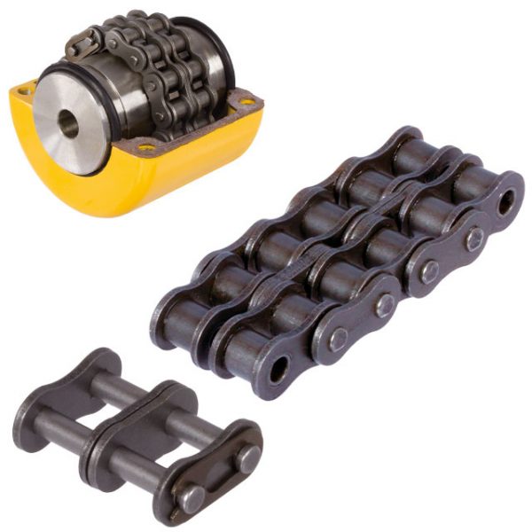
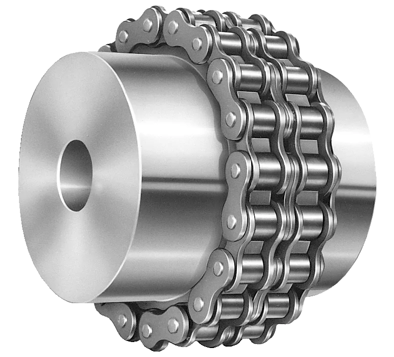
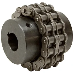
Stainless Steel Coupling Transmission Parts Gear High Quality Good Price Gear Roller Chain Couplings Nm Flange Flexible Elastomeric Stainless Steel Coupling
We are the leading top Chinese coupling manufacturer, and are specializing in various high quality coupling.
1. Material: Cast iron, Rubber.
2. OEM and ODM are available
3. High efficient in transmission
4. Finishing: Painted.
5. High quality with competitive price
6. Different models suitable for your different demands
7. Stock for different bore size on both sides available.
8. Application in wide range of environment.
9. Quick and easy mounting and disassembly.
10. Resistant to oil and electrical insulation.
11. Identical clockwise and anticlockwise rotational characteristics.
12. Small dimension, low weight, high transmitted torque.
13. It has good performance on compensating the misalignment.
Fluid couplings:
Features:
Improve the starting capability of electric motor, protect motor against overloading, damp shock, load
fluctuation and torsional vibration, and balance and load distribution in case of multimotor drives.
Applications:
Belt conveyers, csraper conveyers, and conveyers of all kinds Bucket elevators, ball mills, hoisters, crushers,
excavators, mixers, straighteners, cranes, etc.
Flange Flexible Coupling:
Flexible Coupling Model is widely used for its compact designing,easy installation,convenientmaintenance,small size and
light weight.As long as the’relative displacement between shafts is kept within the specified tolerance,the coupling will
operate the best function and a longer working life,thus it is greatly demanded in medium and minorpower transmission
systems drive by moters,such as speed reducers,hoists,compressor,spining &weaving machines and ball mills,permittable
relative displacement:Radial displacement 0.2-0.6mm ; Angel displacemente 0o 30′–1o 30′
Jaw Couplings:
Click here for more types of couplings
Our Services:
1.Design Services
Our design team has experience in cardan shaft relating to product design and development. If you have any needs for your new product or wish to make further improvements, we are here to offer our support.
2.Product Services
raw materials → Cutting → Forging →Rough machining →Shot blasting →Heat treatment →Testing →Fashioning →Cleaning→ Assembly→Packing→Shipping
3.Samples Procedure
We could develop the sample according to your requirement and amend the sample constantly to meet your need.
4.Research & Development
We usually research the new needs of the market and develop the new model when there is new cars in the market.
5.Quality Control
Every step should be special test by Professional Staff according to the standard of ISO9001 and TS16949.
Company Information:
Can chain couplings be used in high-speed applications?
Chain couplings can be used in certain high-speed applications, but there are limitations and considerations that need to be taken into account. The suitability of chain couplings for high-speed applications depends on factors such as the specific design of the coupling, the chosen chain type, and the operating conditions. Here are some key points to consider:
- Coupling Design: The design of the chain coupling plays a crucial role in determining its suitability for high-speed applications. High-speed chain couplings typically incorporate features that minimize vibration, reduce stress concentrations, and ensure smooth operation. Couplings designed for high-speed use may have additional balancing or damping mechanisms to counteract potential issues associated with centrifugal forces and resonance.
- Chain Type: The type of chain used in the coupling can affect its performance at high speeds. In general, roller chains are commonly used in chain couplings. However, for high-speed applications, special high-speed roller chains or other chain types designed for increased rotational speeds may be required. These chains are designed to minimize friction, reduce wear, and handle the centrifugal forces associated with high-speed operation.
- Bearing Selection: Proper bearing selection is critical for high-speed chain couplings. The bearings used in the coupling should be capable of handling the anticipated speeds and dynamic loads. High-quality, precision bearings with appropriate lubrication are typically necessary to ensure smooth operation and minimize the risk of premature failure.
- Balancing and Vibration: High-speed chain couplings should be properly balanced to minimize vibration and ensure stable operation. Imbalances in rotating components can lead to increased noise, excessive stress, and reduced service life. Balancing techniques such as dynamic balancing or the use of counterweights may be employed to achieve smooth and reliable operation.
- Lubrication: Adequate lubrication is crucial for high-speed chain couplings to minimize friction, reduce wear, and dissipate heat effectively. Proper lubrication practices, including the use of high-quality lubricants and regular maintenance, should be followed to ensure optimal performance and prevent premature failure.
Despite these considerations, it’s important to note that chain couplings may have practical limitations in terms of maximum allowable speeds. The specific speed limitations will depend on factors such as the coupling design, chain type, size, and the operating conditions. It is advisable to consult the manufacturer’s specifications and guidelines to determine the maximum recommended speed for a particular chain coupling.
In certain high-speed applications where chain couplings may not be suitable, alternative coupling types such as flexible disc couplings, gear couplings, or elastomeric couplings specifically designed for high-speed applications may be more appropriate. These couplings are engineered to handle the challenges associated with high rotational speeds, offering improved balance, reduced vibration, and higher speed capabilities.
Overall, when considering the use of chain couplings in high-speed applications, it is essential to carefully evaluate the specific requirements, consult with the manufacturer, and ensure that the coupling is designed and selected to operate safely and reliably at the desired speeds.
What is the maximum torque capacity of a chain coupling?
The maximum torque capacity of a chain coupling can vary depending on several factors, including the size and design of the coupling, the type and quality of the components used, and the application requirements. It is important to refer to the manufacturer’s specifications and guidelines for the specific chain coupling being used. These specifications typically provide the maximum torque capacity or the maximum allowable torque for the coupling.
The maximum torque capacity is usually expressed in torque units, such as Newton-meters (Nm) or foot-pounds (ft-lb). It represents the maximum amount of torque that the chain coupling can transmit without exceeding its design limits or risking premature failure.
When selecting a chain coupling, it is crucial to consider the torque requirements of the application and choose a coupling with a sufficient torque capacity. Factors such as the power requirements, operating conditions, and misalignment tolerance should be taken into account to ensure that the selected coupling can handle the required torque.
It is important to note that exceeding the maximum torque capacity of a chain coupling can lead to various issues, including accelerated wear, excessive stress on the components, and potential coupling failure. Therefore, it is recommended to always operate the chain coupling within its specified torque limits to maintain its reliability and longevity.
For accurate and precise information regarding the maximum torque capacity of a specific chain coupling, it is necessary to consult the manufacturer’s documentation or contact the manufacturer directly. They can provide detailed information based on the specific design and specifications of the coupling.
How does a chain coupling work?
A chain coupling works by connecting two rotating shafts using a roller chain and sprockets. The sprockets have teeth that engage with the rollers of the chain, creating a positive drive mechanism.
When the first shaft rotates, it drives the sprocket attached to it. The engaged chain then transfers the motion to the second sprocket and the second shaft, causing it to rotate as well.
The chain coupling design allows for flexibility and misalignment compensation. In the presence of angular misalignment between the shafts, the chain can accommodate the deviation by flexing and adjusting its position on the sprockets. Similarly, if there is parallel misalignment or axial displacement, the chain coupling can flex and adjust to maintain proper engagement and transmit torque between the shafts.
The engagement between the sprocket teeth and the chain rollers ensures a positive drive, meaning that the torque from the driving shaft is efficiently transferred to the driven shaft. This makes chain couplings suitable for applications where high torque loads need to be transmitted.
Proper lubrication is essential for the smooth operation and longevity of a chain coupling. Lubricants such as oil or grease are applied to the chain and sprockets to reduce friction and wear. The lubrication helps prevent heat buildup and ensures the chain and sprockets rotate smoothly, minimizing power losses and extending the lifespan of the coupling.
In summary, a chain coupling operates by using a roller chain and sprockets to connect two rotating shafts. The engaged chain transfers torque from the driving shaft to the driven shaft, while accommodating misalignment between the shafts. The positive drive mechanism and the flexibility of the chain make chain couplings effective in transmitting high torque loads while allowing for smooth and reliable power transmission.
editor by CX 2023-09-30
China Custom Flange Cast Iron Coupling Steel Universal Joint Cardan Pump Rubber Motor Disc Curved Tooth Flex Rigid Drive Shaft Nm Yox Fluid Jaw Flexible Chain Gear Couplings
Product Description
Excellent powder metallurgy parts metallic sintered parts
We could offer various powder metallurgy parts including iron based and copper based with top quality and cheapest price, please only send the drawing or sample to us, we will according to customer’s requirement to make it. if you are interested in our product, please do not hesitate to contact us, we would like to offer the top quality and best service for you. thank you!
How do We Work with Our Clients
1. For a design expert or a big company with your own engineering team: we prefer to receive a fully RFQ pack from you including drawing, 3D model, quantity, pictures;
2. For a start-up company owner or green hand for engineering: just send an idea that you want to try, you don’t even need to know what casting is;
3. Our sales will reply you within 24 hours to confirm further details and give the estimated quote time;
4. Our engineering team will evaluate your inquiry and provide our offer within next 1~3 working days.
5. We can arrange a technical communication meeting with you and our engineers together anytime if required.
| Place of origin: | Jangsu,China |
| Type: | Powder metallurgy sintering |
| Spare parts type: | Powder metallurgy parts |
| Machinery Test report: | Provided |
| Material: | Iron,stainless,steel,copper |
| Key selling points: | Quality assurance |
| Mould type: | Tungsten steel |
| Material standard: | MPIF 35,DIN 3571,JIS Z 2550 |
| Application: | Small home appliances,Lockset,Electric tool, automobile, |
| Brand Name: | OEM SERVICE |
| Plating: | Customized |
| After-sales Service: | Online support |
| Processing: | Powder Metallurgr,CNC Machining |
| Powder Metallurgr: | High frequency quenching, oil immersion |
| Quality Control: | 100% inspection |
The Advantage of Powder Metallurgy Process
1. Cost effective
The final products can be compacted with powder metallurgy method ,and no need or can shorten the processing of machine .It can save material greatly and reduce the production cost .
2. Complex shapes
Powder metallurgy allows to obtain complex shapes directly from the compacting tooling ,without any machining operation ,like teeth ,splines ,profiles ,frontal geometries etc.
3. High precision
Achievable tolerances in the perpendicular direction of compacting are typically IT 8-9 as sintered,improvable up to IT 5-7 after sizing .Additional machining operations can improve the precision .
4. Self-lubrication
The interconnected porosity of the material can be filled with oils ,obtaining then a self-lubricating bearing :the oil provides constant lubrication between bearing and shaft ,and the system does not need any additional external lubricant .
5. Green technology
The manufacturing process of sintered components is certified as ecological ,because the material waste is very low ,the product is recyclable ,and the energy efficiency is good because the material is not molten.
FAQ
Q1: What is the type of payment?
A: Usually you should prepay 50% of the total amount. The balance should be pay off before shipment.
Q2: How to guarantee the high quality?
A: 100% inspection. We have Carl Zeiss high-precision testing equipment and testing department to make sure every product of size,appearance and pressure test are good.
Q3: How long will you give me the reply?
A: we will contact you in 12 hours as soon as we can.
Q4. How about your delivery time?
A: Generally, it will take 25 to 35 days after receiving your advance payment. The specific delivery time depends on the items and the quantity of your order. and if the item was non standard, we have to consider extra 10-15days for tooling/mould made.
Q5. Can you produce according to the samples or drawings?
A: Yes, we can produce by your samples or technical drawings. We can build the molds and fixtures.
Q6: How about tooling Charge?
A: Tooling charge only charge once when first order, all future orders would not charge again even tooling repair or under maintance.
Q7: What is your sample policy?
A: We can supply the sample if we have ready parts in stock, but the customers have to pay the sample cost and the courier cost.
Q8: How do you make our business long-term and good relationship?
A: 1. We keep good quality and competitive price to ensure our customers benefit ;
2. We respect every customer as our friend and we sincerely do business and make friends with them, no matter where they come from.
Handling Overloads and Stall Conditions in Fluid Couplings
A fluid coupling is designed to handle overloads and stall conditions in power transmission systems. When an overload or stall occurs, the fluid coupling utilizes its unique operating principle to protect the drivetrain and the connected machinery:
- Slip Feature: One of the key characteristics of a fluid coupling is its ability to slip at high torque loads. When an overload situation arises, the fluid coupling allows some relative motion between the input and output sides, known as slip. This slip absorbs the excess torque and prevents it from being transferred to the driven equipment, effectively protecting it from damage.
- Fluid Circulation: During normal operation, the fluid inside the coupling circulates smoothly between the impeller and turbine, transmitting torque with minimal losses. However, when an overload or stall condition occurs, the fluid circulation may become turbulent, generating heat in the process. This heat dissipation helps in absorbing and dissipating the excess energy, preventing the transmission system from experiencing sudden stress.
- Automatic Reconnection: After an overload or stall condition, once the excess torque is dissipated through slip and heat, the fluid coupling automatically reconnects the input and output sides, resuming the power transmission. This automatic reconnection ensures that the system returns to normal operation once the overload situation is resolved.
- Sturdy Construction: Fluid couplings are designed with robust and durable materials to withstand high torque and thermal stresses during overload conditions. The strong construction ensures that the fluid coupling remains reliable and operational even after multiple overload events.
Overall, a fluid coupling’s ability to handle overloads and stall conditions makes it a reliable and essential component in various industrial applications. By providing overload protection and slip characteristics, fluid couplings help prevent costly damage to equipment, increase operational safety, and contribute to the longevity of the entire power transmission system.

Fluid Couplings for Soft-Start Applications in Conveyor Systems
Yes, fluid couplings are well-suited for soft-start applications in conveyor systems. Soft-starting is the gradual acceleration of the conveyor belt to reduce sudden mechanical stress and current spikes during startup. Fluid couplings provide a smooth and controlled method of power transmission, making them ideal for achieving soft-start capabilities in conveyor systems.
When a conveyor system equipped with a fluid coupling starts, the fluid inside the coupling initially acts as a viscous medium, allowing the input and output shafts to rotate at different speeds. As the fluid coupling fills with fluid, it gradually transmits torque and smoothly accelerates the conveyor belt.
One of the significant advantages of using fluid couplings for soft-start applications is that they provide adjustable startup times. By controlling the amount of fluid inside the coupling, the startup acceleration rate can be precisely tuned to match the specific requirements of the conveyor system.
The soft-start feature offered by fluid couplings helps in several ways:
- Mechanical Stress Reduction: The gradual acceleration minimizes mechanical stress on the conveyor belt, pulleys, and other components, leading to extended equipment life and reduced maintenance costs.
- Energy Savings: Soft-starting prevents sudden current spikes and reduces the power demand during startup, resulting in energy savings and improved efficiency.
- Improved Conveyor Belt Life: By avoiding abrupt starts, the wear and tear on the conveyor belt are reduced, leading to longer belt life and decreased downtime.
- Enhanced Conveyor Control: Soft-start capabilities enable better control over the conveyor system, allowing operators to optimize the material flow and prevent product spillage or jamming.
Fluid couplings offer reliable and cost-effective soft-start solutions for conveyor systems across various industries, including mining, manufacturing, and material handling. They are particularly beneficial when dealing with heavy loads or long conveyor belts, where the avoidance of sudden shock loads is critical.
In summary, fluid couplings are a popular choice for soft-start applications in conveyor systems due to their smooth and controlled power transmission, adjustable startup times, and the ability to reduce mechanical stress and energy consumption during startup.
Can Fluid Couplings be Retrofitted into Existing Machinery?
Yes, fluid couplings can be retrofitted into existing machinery in many cases. Retrofitting is a process of adding new components or technologies to existing equipment to improve its performance or functionality. Fluid couplings are versatile and can often be integrated into various industrial machines and power transmission systems.
The process of retrofitting a fluid coupling involves several steps:
- Evaluation: Before retrofitting, a thorough evaluation of the existing machinery is necessary. Engineers need to assess the machine’s design, power requirements, and other relevant factors to determine the suitability of a fluid coupling.
- Compatibility: Fluid couplings should be compatible with the existing machine’s shaft, motor, and driven equipment. If necessary, modifications may be required to ensure a proper fit.
- Installation: The installation process involves mounting the fluid coupling onto the machine’s shaft and connecting it to the motor and driven equipment.
- Alignment: Precise alignment of the fluid coupling is crucial for optimal performance and to avoid issues such as vibration and wear.
- Testing: After installation, the retrofitted system undergoes testing to ensure that it functions as intended and meets the desired performance goals.
Retrofitting fluid couplings can offer various benefits, including:
- Improved Energy Efficiency: Fluid couplings can enhance energy efficiency by reducing power losses and improving the overall power transmission system’s efficiency.
- Enhanced Protection: Fluid couplings provide protection against shocks and overloads, safeguarding the machinery and its components from damage.
- Reduced Maintenance: The smooth start and reduced stress on the machine during operation can lead to lower maintenance requirements and longer equipment lifespan.
- Soft Start: Fluid couplings offer a soft start, which reduces the mechanical stress on the machine during startup, extending its life and minimizing downtime.
However, it is essential to involve qualified engineers and technicians for the retrofitting process to ensure proper installation, alignment, and performance of the fluid coupling in the existing machinery.
editor by CX 2023-09-04
China wholesaler Clamped Compressio Flexible Rubber Motor Quick Release Spline Fluid Shaft Flange Sleeve Split Threaded Stainless Steel Hydrodynamic Custom Rigid Coupling
Product Description
Clamped compressio Flexible Rubber Motor Quick Release Spline Fluid Shaft flange sleeve split threaded stainless steel Hydrodynamic custom rigid Coupling
Spline fluid shafts are used in a variety of applications, including:
- Hydraulic pumps and motors
- Gearboxes
- Compressors
- Turbines
- Machine tools
- Robots
- Material handling equipment
- Construction equipment
- Mining equipment
- Aerospace and defense applications
Spline fluid shafts are characterized by their ability to transmit high torque and power while minimizing vibration and noise. They are also relatively easy to manufacture and install, making them a cost-effective solution for a wide range of applications.
Here are some specific examples of how spline fluid shafts are used in different applications:
- In hydraulic pumps and motors, spline fluid shafts transmit the power from the motor to the pump. This allows the pump to operate at high speeds and pressures without the risk of damage.
- In gearboxes, spline fluid shafts transmit the power from the input shaft to the output shaft. This allows the gearbox to change the speed and direction of rotation of the output shaft.
- In compressors, spline fluid shafts transmit the power from the motor to the compressor. This allows the compressor to operate at high speeds and pressures without the risk of damage.
- In turbines, spline fluid shafts transmit the power from the rotating shaft to the generator. This allows the turbine to generate electricity at high speeds and pressures.
- In machine tools, spline fluid shafts transmit the power from the motor to the cutting tool. This allows the cutting tool to operate at high speeds and pressures without the risk of damage.
- In robots, spline fluid shafts transmit the power from the motor to the actuator. This allows the actuator to move the robot arm at high speeds and with precise control.
- In material handling equipment, spline fluid shafts transmit the power from the motor to the conveyor belt. This allows the conveyor belt to move materials at high speeds and with precise control.
- In construction equipment, spline fluid shafts transmit the power from the motor to the hydraulic cylinders. This allows the hydraulic cylinders to lift and move heavy objects at high speeds and with precise control.
- In mining equipment, spline fluid shafts transmit the power from the motor to the drill bits. This allows the drill bits to penetrate hard rock at high speeds and with precise control.
- In aerospace and defense applications, spline fluid shafts are used in a variety of components, including jet engines, helicopter rotors, and missile guidance systems.
Spline fluid shafts are a versatile and reliable component that can be used in a wide range of applications. They are characterized by their ability to transmit high torque and power while minimizing vibration and noise. Spline fluid shafts are also relatively easy to manufacture and install, making them a cost-effective solution for a wide range of applications.
Factors Influencing the Thermal Performance of a Fluid Coupling
The thermal performance of a fluid coupling, specifically its ability to dissipate heat and maintain operating temperatures within acceptable limits, is influenced by several factors:
- Power Rating: The power rating of the fluid coupling, which indicates its capacity to handle a specific amount of power, affects its thermal performance. Higher power ratings generally result in higher heat generation, so it’s essential to choose a fluid coupling with an adequate power rating for the application.
- Operating Speed: The operating speed of the fluid coupling is a critical factor. Higher speeds can lead to increased heat generation due to friction and viscous losses. It’s essential to consider the operating speed to ensure the fluid coupling can handle the heat produced at the given speed.
- Ambient Temperature: The ambient temperature of the environment in which the fluid coupling operates also plays a role in its thermal performance. Higher ambient temperatures can impact the cooling efficiency and may lead to increased operating temperatures.
- Load Variation: Applications with varying loads can experience changes in heat generation. Fluid couplings used in such systems must be capable of handling the thermal effects of load fluctuations without exceeding temperature limits.
- Cooling Method: The cooling method employed in the fluid coupling design significantly affects its thermal performance. Some fluid couplings use natural convection for cooling, while others incorporate forced cooling methods such as internal or external cooling circuits. The cooling system’s efficiency directly impacts the ability to dissipate heat effectively.
- Fluid Properties: The properties of the fluid inside the coupling, such as viscosity and heat capacity, influence thermal performance. The choice of fluid can affect the amount of heat generated and the efficiency of heat dissipation.
- Operating Time: The duration of operation also affects the thermal behavior of the fluid coupling. Continuous operation or extended duty cycles may lead to higher operating temperatures, requiring careful consideration during selection.
- Proper Maintenance: Regular maintenance, including lubricant inspection and replacement, is crucial for optimal thermal performance. Contaminated or degraded fluid can impact the heat transfer characteristics of the coupling.
It’s essential to consider these factors when selecting a fluid coupling to ensure that it can effectively manage heat generation and maintain safe operating temperatures in the specific application.
Contribution of Fluid Coupling to the Overall Efficiency of a Mechanical System
A fluid coupling plays a crucial role in improving the overall efficiency of a mechanical system, especially in applications where smooth power transmission, soft-starting, and torque control are essential. Here’s how a fluid coupling contributes to system efficiency:
1. Smooth Power Transmission:
Fluid couplings provide a smooth and gradual transfer of power from the driving to the driven machinery. The absence of direct mechanical contact between the input and output shafts reduces shock loads and vibrations, leading to less wear and tear on the connected equipment. This smooth power transmission results in increased system efficiency and reduced downtime.
2. Soft-Start Capability:
Fluid couplings offer soft-starting functionality, which is particularly beneficial for high-inertia or heavy-load applications. During startup, the fluid coupling allows the input shaft to gradually accelerate the output shaft, preventing sudden jerks or torque spikes. Soft-starting not only protects the mechanical components but also reduces energy consumption during the starting phase, contributing to overall efficiency.
3. Torque Control:
Fluid couplings enable precise control over the torque transmitted between the driving and driven machinery. By adjusting the fill level or using variable speed couplings, the torque output can be fine-tuned to match the requirements of the application. This feature ensures optimal performance and energy efficiency, especially in systems where torque demand varies during operation.
4. Overload Protection:
In case of sudden overloads or jamming of the driven machinery, the fluid coupling acts as a torque limiter. It will slip and absorb excess torque, protecting the mechanical system from damage. This overload protection not only safeguards the equipment but also contributes to the longevity and efficiency of the entire system.
5. Heat Dissipation:
Fluid couplings can absorb and dissipate heat generated during continuous operations. This heat dissipation capability prevents the system from overheating, ensuring consistent performance and avoiding thermal damage to the machinery. By maintaining proper operating temperatures, the fluid coupling aids in improving overall efficiency.
6. Energy Savings:
With its ability to reduce shock loads and provide smooth acceleration, a fluid coupling can help save energy during starting and stopping cycles. The elimination of mechanical shocks and vibrations reduces energy losses, resulting in higher overall energy efficiency.
In summary, a fluid coupling enhances the overall efficiency of a mechanical system by providing smooth power transmission, soft-start capability, precise torque control, overload protection, heat dissipation, and energy savings. Its contributions to reduced wear and tear, energy-efficient operations, and enhanced equipment lifespan make it a valuable component in various industrial applications.
What is a Fluid Coupling and How Does It Work?
A fluid coupling is a type of hydraulic device used to transmit torque and power between two shafts without direct mechanical contact. It consists of three main components: the impeller, the turbine, and the housing. Fluid couplings are commonly used in various industrial applications, such as heavy machinery, conveyors, and automotive drivetrains.
Working Principle: The fluid coupling operates based on the principle of hydrodynamic power transmission. It uses a hydraulic fluid (usually oil) to transfer torque from the driving shaft (input) to the driven shaft (output).
1. Impeller: The impeller is mounted on the input shaft and is connected to the prime mover (e.g., an electric motor or an engine). When the prime mover rotates the impeller, it creates a swirling motion in the hydraulic fluid.
2. Turbine: The turbine is connected to the output shaft and is responsible for transmitting the torque to the driven system. The swirling motion of the hydraulic fluid generated by the impeller causes the turbine to rotate.
3. Fluid Filling: The area between the impeller and the turbine is filled with hydraulic fluid. As the impeller rotates, it creates a vortex in the fluid, which in turn causes the turbine to rotate.
4. Fluid Coupling Working: As the impeller and turbine are enclosed in the housing, the hydraulic fluid transfers rotational energy from the impeller to the turbine without any direct physical connection. The fluid coupling allows some slip between the impeller and the turbine, which enables smooth torque transmission, dampens shock loads, and provides overload protection.
5. Slip: Under normal operating conditions, there is a slight speed difference (slip) between the impeller and the turbine. This slip allows the fluid coupling to absorb shock loads and dampen vibrations, protecting the connected machinery from sudden jolts and overloads.
Fluid couplings are advantageous in applications where a gradual start-up and controlled acceleration are required. They provide a smoother and more flexible power transmission compared to direct mechanical couplings like gear couplings or belt drives.
However, it’s important to note that fluid couplings have some energy loss due to the slip, which can result in reduced efficiency compared to direct mechanical couplings like gear couplings or belt drives.
editor by CX 2023-08-09