We warmly welcome prospects each in your own home and abroad to speak to us to negotiate company, exchange facts and cooperate with us. We specializing inside the manufacturing of Agricultural Gearbox, PTO Shafts, Sprockets, Fluid Coupling, Worm Gear Reducers, Gears and racks, Roller Chains, Sheave and Pulleys, Planetary Gearboxes, Timing Pulleys, Shaft Collars and even more. Involve one particular 0.5 modulus brass worm gear shaft and one particular 20 teeth brass worm gear wheel. The transmission structure of worm shaft is simple, compact, smaller volume and light weight. Worm Shaft Z1=1, flip a round of worm gear teeth, could get a large transmission ratio, usually during the electrical power CAST IRON WORM GEAR REDUCER The transmission is secure, the vibration, influence and noise are compact, the reduction ratio is huge, the versatility is broad, and it could be utilised with many mechanical tools.
It could possibly obtain a significant transmission ratio with single-stage transmission, and includes a compact framework. Most models have better self-locking efficiency, and will save braking units for mechanical gear with braking necessities. Gears aids us through a mechanism of rotation among two axes to produce energy. So they, with all the assist of rotation following a mechanical concept linked to physics transfers pace into electrical power. They might be of two sizes, 1 small and also the other big, adjoining each other using the assistance of teeth. The teeth are interlocked and induce rotation. WORM GEAR AND Pros OF WORM GEARS If amongst two gears one particular is heavier plus the other lighter it is noted that the weight turns into the terrific issue to result in friction. If the weight appears too heavy rotation could be hampered leading to inconvenience to move the machine with which they are attached.
Different gears have unique teeth. The teeth are inside a twisted kind or within a straight form. It’s the action of a helical one particular to radiate motion amongst two shafts. Whereas the bevel kind has teeth according to conical surface. The shafts are never parallel and intersected sharply in an angle. WORM GEAR Pace REDUCER Market Velocity REDUCER FOR Electric MOTOR Two or 3 reducers can be utilized to type a multi-stage reducer to acquire a great gear ratio. A worm, in industrial parlance, is actually a shaft that has a helical thread. It truly is normally a part of a gear that meshes by using a toothed wheel. Worm gears then again, are these acknowledged as worm wheels. Sometime quite a few people today are baffled using the terms worm, worm gear and worm drive, pondering that these 3 imply the identical thing.
Worm gears are important especially when there may be a need to reduce the gear size. It’s the worm which has the capacity for making the gear rotate and not the other way all over. Using the shallow angle within the worm, the gear won’t have the capacity to rotate it.
Forms of worm gear
You can find essentially 3 different kinds of worm wheels: the non-throated; single throated; and double throated. Non-throated worm wheels are individuals that don’t have throats in the two the worms along with the gear. Single throated classes are individuals whose gears are throated. Lastly, double throated ones are people with throated worms and gears.
Worm gear characteristics
You will discover notable traits of a worm wheel. 1st, it has the capability to transfer and carry load with utmost accuracy. It’s also most effective for massive velocity reductions. The efficiency of your worm gear, on the other hand, depends upon installation problems, the worm’s lead angle, sliding velocity, surface high-quality and lubricant selection.
Producing worm gears grow to be helpful
A system acknowledged as double enveloping helps make worm gearing become much more efficient. This engineering enhances the current characteristics on the worm wheel. This prospects to far better accuracy and improved torque. What helps make the system so particular may be the undeniable fact that it might be utilised to produce improved lubrication and design and style while loads are divided in each with the gear’s teeth. Worm gear applications
Worm wheels make conveyor methods do its perform. Conveyors are equipment to transfer 1 materials from one particular area to one more. Apart from conveyor methods however, the worm wheel may also be used in substantial overall performance motor vehicles.
Hollow Pin Chains 08BP 40HP, 50HPSS, 60HP, 12BHP, 80HP, C2040HP, C2050HP, C2060HP, C2080HP, HB50.8, C2042HP, C2052HP, C2062HP, C2082HP, C2042H-HP, C2052H-HP, C2062H-HP, C2082H-HP Stainless Steel Roller Chain Stainless Steel Conveyor Chain Stainless Steel Roller Chains,Stainless Steel Conveyor chain, Stainless steel chain for bottle conveyor line that is applied on bottle filling conveyor lines, other typical ss chain or distinctive ss chains (SS304 chain, SS316 chains, SS316L chains, SS conveyor chains, SS304 conveyor chain, SS316 conveyor chain) all obtainable Rust 304 Stainless Steel Chain/Lifting Chain Rigging Hardware, More than 1000’s Wide range. Like Connecting Website link, Safety Hook, Eye Hook, Clevis Hook, Master Link, Master Link Assembly, And so on. Series Zinc plated Agricultural Transmission Chain for Feeder residence Clear Grain Attachment: K1, K5, K19, K30, K39, 220B, F4, F5, F14, F45, G18, TM91E, TM92, C6E, C11E, C13E, C30E, CPE, LV41N, Surface Remedy: Shot-Peening, Zinc plated. Application: extensively utilised in Feeder home, Clear Grain, Return Grain in agricultural machine. CC600 Corrosion Resisting Cast iron Chain Our CC 600 Conveyor chains are manufactured in malleable iron with steel pins, with pins which can be unhardened. This established design and style results in an assembled chain which is hugely sturdy and put on resistant. Built withing the gasoline bottling industry (Exclusively Liquid Petroleum Fuel ) our CC600 series remains a products of 1st selection for distributors and finish end users alike, the place a high quality solution is needed 1st time, every time. The CC600 chains are intended for use in multistrand conveyors dealing with individual loads beneath circumstances of mild corrosion. They may be ordinarily supported in channels and therefore are hugely flexible, making it possible for for fluid motion and flexibility when essential. This versatility allows them to be used inside a number of hefty duty applications but their main application is in the bottling business in which they may be termed on to deal with crates and gasoline bottles. specializes in creating all sorts of mechanical transmission products and hydraulic transmission merchandise, this kind of as planetary gearboxes Chains are series of linked back links or rings which have been normally created of metal and might be connected or fitted into one another. Each and every piece with the chain can have in excess of one particular website link depending on its application. Some makes use of of chains could be for fastening, binding or supporting objects. The two most typical variations of making chains are roller chains and those who are torus shaped. The kind of the chain depends on the application from the chain. Torus shaped chains are extremely popular in lots of applications. They’re able to be made use of for hoisting, securing or supporting and have a really very simple form of rings which have been linked to each other. This easy layout offers these chains versatility in two dimensions. Their simple design and versatility make it possible for them to become utilized for many tasks this kind of as securing a bicycle
Roller chains are very frequent in bicycles. They’re created to transfer electrical power in machines. Taking bicycle chains one example is, they’re developed to mesh together with the teeth in the sprockets in the machine. Versatility in these chains can also be limited as they can only move in one direction. Some typical applications of chains is often as critical chains, snow chains and bicycle chains. As stated earlier on this report, bicycle chains are roller chains. They transfer electrical power from pedals on the drive-wheel that in turn propels the bicycle forward. These chains are normally made from plain carbon or an alloy of steel however some might be nickel-plated so as to protect against rust. These chains can also be considered to be really energy efficient. Although numerous people today might count on the efficiency for being significantly affected from the lubricant, a study that was performed in a clean laboratory uncovered that in lieu of lubricants, a larger sprocket would deliver a much more efficient drive. Also, the greater the tension while in the chain, the much more effective it will be.
single row 4 level speak to ball slewing rings is composed of two seat rings, which style and design in compact framework and light fat, steel ball contact using the circular raceway at 4 factors; it may possibly bear the axial force, radial force and the tilting second in the similar time. Coresun drive Single-row four stage speak to ball ring has the features of compact in style, and light in weight. The balls roll to the circular race at 4 factors, so it might undertake the axial force, radial force and tipping minute in the identical time. This series of 4 level make contact with ball bearings are appropriate in lots of engineering machinery, for example rotary conveyor welding operation machine, modest cranes, tiny and medium-sized excavators,slewing conveyer, welding manipulator, light and medium duty crane, and various building machinery. Three types of this type of single row 4 level speak to ball slewing bearing: A. With no gear bearing (non tooth) B. External gear bearing (external tooth) C. Inner gear bearing (internal tooth)
double row unique diameter ball slewing bearing is mostly produced up of in-up ring, in-down ring and outside ring, so balls and spacers is usually directly discharged in to the upper and decrease raceway. Based on worry situations, bearings are organized to two rows of balls of various diameter. This assembly is quite practical. Angle of each upper and decrease raceway is 90??so bearings can bear substantial axial force and resultant torque. Bearing requirements distinctive design when radial force is 0.1 times bigger compared to the axial force. Substantial in sizes and attributes compact in design, bearings are especially application in managing equipments requiring medium above diameter, such as tower crane and mobile crane.
single row cross roller slewing ring is primarily manufactured up of inside and outside rings. It characteristics compact in design and style, light in weight, compact in assembling clearance, and substantial in putting in precision. As the rollers are crossed organized by one:one, it’s ideal for large precision mounting and capable to bear axial force, radial force and resultant torque concurrently. This series single row crossed roller slewing bearing have broadly application in lift transport aircraft, development machinery, and military solutions. 1. Experienced gears manufacturer 2.Experienced in Cooperate with major Businesses 3. Experienced gears Engineering Capability 4.Stable gears High-quality five.Acceptable gears Costs 6.Tiny gears Orders Accepted seven.Constant gears good quality enhancements eight. Large gears high quality Performance 9.Quick gears lead time and shipment ten.Expert gears service We are able to develop six patterns of slewing bearings within a wide variety of specs with diameters ranging from 400 mm to 5050 mm. Our products show each and every day for being vital structural and connection aspects used in wind turbines, excavators, mobile cranes, harbor and shipyard cranes, robots, health-related scanners and in general mechanical engineering. Top quality Management: Good quality may be the key to our achievement. We are committed to achieving customers’ satisfaction by offering high-quality products and services. We make certain that our in depth high-quality management system is in accordance with ISO9001 regular and is performed properly. In pursuit of high-quality raw products, we undergo a stringent verification and choice process to choose the top suppliers of forged rings and other components in China. If necessary, we are able to also apply extra large-diameter forged rings created by ThyssenKrupp in Germany. Cranes are uniquely constructed, which means the slewing ring bearing is surely an important component of its layout. High quality and precision through the manufacturing procedure. Gear transmission refers to your device that transmits movement and power in the gear pair. It is the most extensively employed mechanical transmission process in contemporary products. Its transmission is far more precise, substantial efficiency, compact structure, dependable operation and prolonged services existence.Our gears may be heat treated, hardened, oil immersed in line with buyer requirements.The gear is broadly utilized in field, motor vehicle, energy resources, motor, bicycle, electrombile.
single row four stage speak to ball slewing rings is composed of two seat rings, which style and design in compact structure and light fat, steel ball make contact with together with the circular raceway at four factors; it may possibly bear the axial force, radial force and the tilting minute in the identical time. Coresun drive Single-row four stage make contact with ball ring has the attributes of compact in design, and light in weight. The balls roll to the circular race at four points, so it could undertake the axial force, radial force and tipping second in the exact same time. This series of 4 point get hold of ball bearings are appropriate in lots of engineering machinery, like rotary conveyor welding operation machine, smaller cranes, modest and medium-sized excavators,slewing conveyer, welding manipulator, light and medium duty crane, along with other building machinery. 3 varieties of this sort of single row four level make contact with ball slewing bearing: A. Without the need of gear bearing (non tooth) B. External gear bearing (external tooth) C. Internal gear bearing (internal tooth)
double row different diameter ball slewing bearing is primarily made up of in-up ring, in-down ring and outside ring, so balls and spacers is often straight discharged in to the upper and reduce raceway. In line with pressure conditions, bearings are arranged to two rows of balls of various diameter. This assembly is very effortless. Angle of both upper and reduce raceway is 90??so bearings can bear massive axial force and resultant torque. Bearing requires distinctive design when radial force is 0.1 times more substantial than the axial force. Huge in sizes and options compact in style, bearings are particularly application in managing equipments requiring medium over diameter, for instance tower crane and mobile crane.
single row cross roller slewing ring is mostly created up of within and outdoors rings. It functions compact in design and style, light in weight, tiny in assembling clearance, and higher in putting in precision. Since the rollers are crossed organized by one:1, it really is suitable for substantial precision mounting and capable to bear axial force, radial force and resultant torque concurrently. This series single row crossed roller slewing bearing have extensively application in lift transport aircraft, construction machinery, and military items. one. Experienced gears manufacturer two.Expert in Cooperate with massive Businesses three. Expert gears Engineering Capability 4.Secure gears Top quality five.Sensible gears Rates 6.Modest gears Orders Accepted seven.Steady gears high-quality enhancements 8. Substantial gears high quality Performance 9.Short gears lead time and shipment 10.Specialist gears support We can produce six types of slewing bearings within a variety of specifications with diameters ranging from 400 mm to 5050 mm. Our solutions prove each day to become essential structural and connection aspects used in wind turbines, excavators, mobile cranes, harbor and shipyard cranes, robots, medical scanners and in general mechanical engineering. Quality Handle: Excellent could be the crucial to our accomplishment. We’re committed to obtaining customers’ satisfaction by offering high-quality products and services. We make certain that our thorough high quality management procedure is in accordance with ISO9001 conventional and is carried out correctly. In pursuit of high-quality raw supplies, we go through a stringent verification and assortment process to select the top suppliers of forged rings and other components in China. If essential, we can also apply added large-diameter forged rings produced by ThyssenKrupp in Germany. Cranes are uniquely constructed, which suggests the slewing ring bearing is surely an crucial component of its design. High-quality and precision during the manufacturing system. Gear transmission refers for the device that transmits motion and energy in the gear pair. It’s the most broadly utilized mechanical transmission approach in contemporary tools. Its transmission is more exact, higher efficiency, compact construction, reliable operation and lengthy services daily life.Our gears might be heat treated, hardened, oil immersed according to customer needs.The gear is widely utilized in industry, vehicle, energy equipment, motor, bicycle, electrombile.
Nylon gear racks is applied on sliding gate, There’s steel core within it. we exported to Europe in significant amount. There’s steel core within the nylon gear rack.You’ll find two items accessible. You’ll find 4 eye(4 bracket is light form) and 6 eyes(6 brackets is heavy sort).Just about every piece of nylon gear rack with screw set Producer supplier exporter of gear rack We exported gear rack in huge quantity to Europe, America, Australia, Brazil, South Africa, Russia etc. There is common gear rack readily available as well as special gear rack as per your drawing or samples. Our gear racks produced by CNC machines There is lots of sizes of steel gears rack for sliding door also. M4 8?¨¢30, M4 9?¨¢30, M4 10?¨¢30, M4 11?¨¢30, M4 12?¨¢30, M4 20?¨¢20, M4 22?¨¢22, M6 30?¨¢30 and so on For M4 8?¨¢30, M4 9?¨¢30, M4 10?¨¢30, M4 11?¨¢30, M4 12?¨¢30, 1M length have 3 bolt,nut, washer sets and just about every 4pcs or 6pcs packed into carton box and then put into steel pallet. For M4 8?¨¢30, M4 9?¨¢30, M4 10?¨¢30, M4 11?¨¢30, M4 12?¨¢30, 2M length have four bolt,nut, washer sets. We will also supply the sliding gate aspect such as sliding door pulley, wheel, roller and so forth. Please kindly verify and allow me know your detail request In case you want 2M or 3M, or any other length, we will create as per your requests Most of our purchaser will send us drawing and we can generate as per your drawing or sample. We produce Module M1-M8 racks, CP and DP British standard racks. The utmost length with the rack is 2 meters. Our items are widely utilized in numerous fields this kind of as automatic doors, window openers, engraving machines, lifters, escalators, automated warehousing, food machinery, power tools, machine equipment, precision transmission, etc.
We exported gear rack in large amount to Europe, America, Australia, Brazil, South Africa, Russia and so on. There is certainly common gear rack offered and in addition special gear rack as per your drawing or samples. Our gear racks produced by CNC machines.
Our gear racks are utilised for window machine, engraving machine, lift machine, opener rack, CNC machine, car, industrial utilization so on. 1) Our gear rack is generated as per DIN requirements by CNC machine two) The stress angle: 20??/14.5?? 3) Module: M0.4-M36/DP1-DP25 four) The maximum length is often 3500mm 5) The material may be Q235, C45, SS304, SS316L, aluminum, copper, nylon and so on. Our gear racks are employed for window machine, engraving machine, lift machine, opener rack, CNC machine, automobile, industrial utilization so on. Industrial Gear Rack Lorem ipsum dolor sit amet, consectetur adipiscing elit, sed do eiusmod tempor incididunt ut labore et dolore magna aliqua.
We can also provide Construction lift gear rack,American conventional gears racks,steel gear rack,helical gear rack,flexible gear racks,power steering rack,steering gear rack ,stainless steel gear rack ,round rack gear ,nylon gear rack ,spur gear rack ,boston gear rack ,audia gear rack ,gears racks ,rack and pinion gear 1. Rich marketplace encounter due to the fact 1988. two. Wide arrange merchandise line, which includes plastics sheet/rod/parts/accessories: MC NYLON, OIL NYLON, POM, UHMW-PE, PU, PETP, Pc, PTFE, PVDF, PPS, PEEK, PAI, PI, PBI ect. three. Manufacture, layout and processing services as per your demand 1. Good Tensile power; 2. Substantial impact and notching influence power; 3. High heat deflection temperature ; 4. Large strength and stiffness; 5. Great glide and limp property characters; six. Superior chemical stability against natural solvents and fuels; seven. Resistant to thermal aging (applicable temperature concerning -50??C and 110??C; 8. Size alternation by humidity absorption has to be thought of;
Shaft sleeve, bearing bush, lining, lining plate, gear; Worm gear, roller copper guidebook rail, piston ring, seal ring, slide block; Spheric bowl, impeller, blade, cam, nut, valve plate, Pipe, stuffing box, rack, belt pulley, pump rotor, etc.rack pinion gear for elevator in stockoperator Steel and Nylon gear rack SPUR GEAR RACK AND PINION nylon gear rack iron gear rack We warmly welcome clients both at your house and abroad to contact us to negotiate enterprise, exchange facts and cooperate with us.
IN CNC GEAR Manufacturing PLANT, Above Ten OF GEARS Building LINES: Gear turning,hobbing,shaving,shaping,grinding,slotting, broaching , we?¡¥ve made substantial investment..
Our substantial precision gear can preserve a substantial top quality prodcuts.CAN DO All the HEATING Course of action: CARBURIZING/CARBONITRIDING/QUENCHING/NORMALIZING/ANNEALING/REHEATING two sets of UBE series multi-purpose chamber(IQ) Japan furnace; 2 sets of German Ipsen environment furnace lines.
9 ton of steel capacity for heat treatment daily. Low CARBON STEEL METAL GEARS Small,Modest STEEL METAL SPUR GEARS! From easy 2-axis turning to 7-axis, turn-mill-drill CNC Swiss-type machines, we’re equipped using a total line of CNC gear from your following manufactures: molding machines/ stamping machines automatic lathe machines/ spring machines. Surface: as your necessity OUR CLEANSES one.Material:C 45# steel ,stainless steel or other essential materials. two.Sprockets is usually made according the customer?¡¥s drawings Our key products: Ultra substantial molecular weight polyethylene, MC nylon, PA6, POM, HDPE, PP,PU, Computer, PVC, ABS, ACRYLIC,PTFE, PEEK, PPS,PVDF. 3.Heat treatment method: Hardening and Tempering, High Frequency Quenching, Carburizing Quenching and so forth according the requirements..
4. Inspection: All items are checked and examined totally all through just about every doing work process and soon after manufacturing will probably be reinspected. Gear transmission refers for the device that transmits movement and electrical power through the gear pair. It can be probably the most extensively employed mechanical transmission method in present day products. Its transmission is much more precise, substantial efficiency, compact structure, reliable operation and extended support lifestyle.
Our gears could be heat taken care of, hardened, oil immersed according to consumer requires.
The gear is widely made use of in market, automobile, power equipment, motor, bicycle, electrombile. Substantial PRECISION Customized SPUR HELICAL GEAR Spur gears are widely accepted since the most efficient variety of gearing solution, when the application of transmitting power and uniform rotary motion from a single parallel shaft to another is required. Determined from the center distance, spur gears build a regular functioning pace drive. This drive velocity can be decreased or improved from the variable quantity of teeth that exist in the driving gear. Style: BEVEL GEAR Manufacturing Process: Minimize Gear Toothed Portion Shape: Bevel Wheel Key Purchaser: Electrical tool factory Export Markets: Worldwide Smaller PINION STEEL DOUBLE SPUR GEAR Zn-plating, Ni-plating, Cr-plating, Tin-plating, copper-plating, the wreath oxygen resin spraying, the heat disposing, hot-dip galvanizing, ELECTROPLATING, ANODIZING Etc. Black oxide coating, painting, powdering, shade zinc-plated, blue black zinc-plated, rust preventive oil, titanium alloy galvanized, silver plating, plastic,We will make customers?¡¥ satisfactory solutions according to your samples or drawings supplied by consumers. For the completion of the item, we also need to learn his material, heat therapy prerequisites and surface treatment method necessities. We’re a factory with 40 years of manufacturing practical experience, welcome to seek the advice of. we make use of the newest machining engineering with a wide range of abilities to meet your demands. Our manufacturing amenities consist of 3-5 axis milling, lathes, grinding, etc, and state on the art metrology. With these machines, we generate complicated components from the most efficient and accurate way. Our manufacturing capabilities enable us to build your part from prototype to mass manufacturing for your most exact of jobs. gear box,gearbox,automatic gearbox,gearbox components,gearbox repairs,steering gear box,reduction gearbox,worm gear,motor gearbox,car or truck gearbox,gearbox store,worm gear box,gearbox makers,box gear,planetary gear box,tiny gearbox,helical gearbox,dc gear motor,gear motor,gear reducer,helical gear box,vehicle gear box,gearbox gears,transmission gearbox,reduction gear box,planetary gear,gearbox transmission,vehicle transmission,utilized gearbox for sale,worm gear motor,utilized gearbox,worm gear reducer,transmission gears,planetary gear reducer,replacement gearbox,mini gearbox
PTO is really a splined drive shaft that is certainly normally positioned on tractors or may be utilized to provide electrical power backup to a separate machine.
The PTO shafts that we offer you comprises of two carden joints and telescopic couplings. Tractor side and implement side would be the two ends of those shafts. The implement side features a shear bolt sort yoke and comes with security guards. 1, Material: Carbon steel/ stainless steel/ aluminum alloy/ copper/bronze/iron/etc.
2, OEM or as per sample or drawing 3, Surface: Blacking, Polishing, Anodize, Chrome plating, Zinc plating, Nickel plating, Tinting, Electrical power coating and so forth.
four, Method: Forging, Stamping, Machining, Metalworking, Sheet Metal Bending, Surface Remedy, Heat Remedy, Gridding, Milling, wire EDM, Linear Cutting and so forth.
5, Precision: OEM/ODM is available The electrical power take-off (PTO) is actually a sophisticated mechanism, enabling implements to draw power from the engine and transmit it to a further application. It will work as being a mechanical gearbox which could be mounted over the vehicle?¡¥s transmission. CHINA FACTORY LARGEBRASS MILLING AND ALUMINUM CASTING MOLDS Manufacturer We are the producer to produce Japanese tractor spare elements,specially for kubota,iseki,yanmar,etc. We’re supplying and exporting Japanese tractor components as the following versions ¡§C Kubota model: B5000, B7000, B1400, B1600 ¡§C YM model: YM F14, YM1100, YM F1401/1901,YM F35 ¡§C Iseki model: TX1300, TX1410,TU1400-1500 UNIVERSAL JOINT MECHANICAL COMPORENTS MACHINE TRACTOR PTO SHAFT Parts UNIVERSAL JOINT Tubes or Pipes
We?¡¥ve previously acquired Triangular profile tube and Lemon profile tube for all of the series we deliver.
And we have some star tube, splined tube and various profile tubes but only for a particular sizes. We specializing from the production of Agricultural Gearbox, PTO Shafts, Sprockets, Fluid Coupling, Worm Gear Reducers, Gears and racks, Roller Chains, Sheave and Pulleys, Planetary Gearboxes, Timing Pulleys, Shaft Collars and much more. 5 End yokes
We have acquired 13 kinds of splined yokes and eight varieties of plain bore yokes. I’ll suggest the normal sort for the reference.
You can also send drawings or images to us in case you are not able to uncover your item in our catalog.
6 Safety gadgets or clutches
I will attach the specifics of security devices for your reference. We have by now have No cost wheel (RA), Ratchet torque limiter(SA), Shear bolt torque limiter(SB), 3types of friction torque limiter (FF,FFS,FCS) and overrunning couplers(adapters) (FAS).
7 For just about any other a lot more unique necessities with plastic guard, connection method, shade of painting, package deal, etc., please really feel cost-free to let me know. The Gearboxes are developed for connecting gear pumps to farm tractor energy consider offs (PTO). Output speed of energy get offs is 540rpm which could be compared with all the good operating speeds of hydraulic pumps. Unique input operating speeds could also be suitable,offered that the PTO gearbox output pace doesn’t exceed 3000 rpm. Housing Created in shell-cast aluminum or in higher mechanical resistance cast iron. Torques The torque figures stated inside the technical charts of every one of the PTO Gearboxes refer to constant duty cycles. Torques beneath intermittent doing work circumstances might be exceeded by 20%. Upkeep Please check out the oil degree by way of the unique oil window every single 50 hrs. Operating temperatures need to not exceed 120 degrees celcius underneath continuos duty cycle. 1. Tubes or Pipes We have presently received Triangular profile tube and Lemon profile tube for each of the series we supply. And we’ve got some star tube, splined tube as well as other profile tubes needed by our consumers (for any particular series). (Please discover that our catalog doesnt have all of the things we create) If you need tubes apart from triangular or lemon, please deliver drawings or pics.
two.End yokes We have received numerous sorts of speedy release yokes and plain bore yoke. I will recommend the usual kind to your reference. You could also send drawings or pictures to us when you cannot come across your item in our catalog.
3. Safety units or clutches I will attach the specifics of safety units for the reference. We’ve previously have No cost wheel (RA), Ratchet torque limiter(SA), Shear bolt torque limiter(SB), 3types of friction torque limiter (FF,FFS,FCS) and overrunning couplers(adapters) (FAS).
4.For almost any other much more specific demands with plastic guard, connection process, shade of painting, package, and so on., please really feel no cost to let me know.
Capabilities: one. We’ve been specialized in creating, manufacturing drive shaft, steering coupler shaft, universal joints, which have exported towards the USA, Europe, Australia and so forth for a long time two. Application to all types of standard mechanical predicament 3. Our items are of high intensity and rigidity. four. Heat resistant & Acid resistant 5. OEM orders are welcomed The Gearboxes are made for connecting gear pumps to farm tractor electrical power get offs (PTO).Output pace of power consider offs is 540rpm which can be in contrast together with the suitable running speeds of hydraulic pumps.Distinctive input operating speeds could also be suitable,presented the PTO gearbox output pace doesn’t exceed 3000 rpm.
Gears Manufactured in Steel UNI 18 PCR M03.Stub teeth guarantee very high resistance and run very quietly.
Shafts Produced in steel UNI 16 CRN4.They are coupled with splined gears and are intended to stand the torque values stated inside the catalogue.
Lubrication 90 gear oil must be put from the pto gearbox prior to use, change the oil after the first 60-80 hours and then each and every 12 months or 1500 hours which ever falls first.
Servicing Please check out the oil degree by means of the distinctive oil window each 50 hrs.Operating temperatures must not exceed 120 degrees celcius below continuos duty cycle.
We specializing while in the manufacturing of Agricultural Gearbox, PTO Shafts, Sprockets, Fluid Coupling, Worm Gear Reducers, Gears and racks, Roller Chains, Sheave and Pulleys, Planetary Gearboxes, Timing Pulleys, Shaft Collars and much more. Taper Lock Pulley V Belt Pulley We give higher good quality Taper Lock Pulley V Belt Pulley in competitive selling price v pulley, v belt pulleys, taper lock pulley,v belt pulleys ,v pulley,v groove pulleys,v groove belt pulley,taper lock pulley,taper lock v belt pulleys,taper lock bushing pulley,taper lock pulleys/ taper bore pulley,huge v belts pulley,double v belts pulley,cast iron v belt pulleys belt pulley,variable velocity v belt pulley,v belt pulley split pulley,cast iron v belts pulley V-BELT PULLEY INTRODUCE: V- belt pulley of various forms ( as outlined by style and width of belts). The material employed is cast iron EN-GJL-250 UNI EN 1561, and for only some forms it is actually steel C45 E UNI EN 10083-1. They have a tiny prebore that will be machined as outlined by customers?¡¥ prerequisites. Additionally by far the most common kinds are available also with taperlock bore. V BELT PULLEY Specs a) Vbelt pulley for taper bushing: SPZ, SPA, SPB, SPC b) Adjustable pace V-belt pulleys and variable pace pulleys c) Flat belt pulleys and conveyor belt pulleys ?¡è AMERICAN Common: a) Sheaves for taper bushing: 3V, 5V, 8V b) Sheaves for QD bushings: 3V, 5V, 8V c) Sheaves for split taper bushing: 3V, 5V, 8V ?¡è We are able to Supply THE RANG Size DIAMETER 62MM~2000MM d) Sheaves for 3L, 4L or possibly a, and 5L or B belts: AK, AKH,2AK, 2AKH, BK, BKH,2BK, 2BKH, 3BK e) Adjustable sheaves: poly V-pulley, multi-pitch H, L, J, K and M High-quality Timing Pulley Light Excess weight Industrial Nylon Plastic Pulley V Belt Pulley 1.Materials: Aluminium alloy,Carton steel, Cast iron, Stainless steel timing belt pulleys two.Surface treament: Anodizing, Blackening, Zinc Plating, Phosphatiing three. Teeth Quantity from 9 to 216; O.D. from 10mm to 1000mm; four. Timing belt pulleys MXL, XL, L, H and XH; T2.5, T5, T10, AT5,AT10; 3M,5M,8M and 14M S3M, S5M, S8M, 14MGT, 8MGT, RPP8M 5. Taper bush and polit bores 6. Timing pulley bar 3M,5M,8M,MXL,XL,L T2.five T5 T10 AT5 and AT10 1) Reliable layout, appropriate for hefty lifting. two) The bearing housing and steel tube are assembled and welded by using a concentric automated. automobile 4) The bearing finish is constructed to ensure that the roller shaft and bearing is usually firmly connected. air compressors six) Roller and supporting components/materials are manufactured to DIN/ AFNOR/ FEM/ ASTM/ CEMA common. belt conveyor drive drum pulley About roller,we will make gravity conveyor roller,steel conveyor roller,driving roller,light middle duty conveyor roller,o-belt tapered sleeve roller,gravity tapered roller,polymer sprocket roller and so forth. Far more specifics, please get hold of us. Is often utilized for tractors three) Cutting of the steel tube and bearing is performed with the use of a digital car device/machine/equipment.. backyard cutter 5) Fabrication from the roller is effected by an automobile gadget and 100% tested for its concentricity. welcome your vpulley inquiries 7) The casing is manufactured with really composite, anti corrosive alloy. 1) European requirements : a) V-belt pulley for taper bushing: SPZ, SPA, SPB, SPC; as much as 10 grooves
b) Adjustable velocity V-belt pulleys and variable velocity pulley
c) Flat belt pulleys and conveyor belt pulleys
two) American specifications:
a) Sheaves for taper bushing: 3V, 5V, 8V
b) Sheaves for QD bushings: 3V, 5V, 8V
c) Sheaves for split taper bushing: 3V, 5V, 8V
d) Sheaves for 3L, 4L or maybe a, and 5L or B belts: AK, AKH, 2AK, 2AKH, BK, BKH,2BK, 2BKH, 3BK
e) Adjustable sheave: poly V-pulley, multi-pitch H, L, J, K and M Why Opt for Us one) Practical experience in casting for more than 15 many years and served buyers all all over the entire world. two) Typical material as outlined by technical drawing 3)Stable quality four) On-time delivery 5) Competitive selling price and good service six) Favourable buyer feedback from domestic and global marketplace seven) Global advanced-level tools which include CNC, numerical lathes, furnance, welding tools, CMM and detect &testing tools we utilized to guarantee our product?¡¥s high-quality. 8) OEM support, your demand is our pursued. 9) ISO9001:2008 and TS16949 quality control 10) Common: ASTM BS DIN etc
TheEPG Auger Drive is heavy duty created and developed in a chopping edge facility. EPG partnered with professional CHINA to develop the really ideal Skid Steer Auger Drive the North American market has to offer you. The outcome is an intense Auger Push, accessible in a few types, with significant torque for every foot abilities. Useless to say, EPG is very delighted. EPG buys right from the supply and through an distinctive partnership with Skid Steer Answers, is able to supply manufacturer charges, with no the conventional distributor mark-up.
Decide on Product Possibilities Over
Choose Auger Push Model Pick an Excavator Auger Cradle (Generate Only choice obtainable) Decide on an Optional Auger Stump Planer (click for specifics) Choose an optional Auger Little bit Select a 2nd optional Auger Little bit
The CHINA developed planetary gearbox delivers an enormous sum of torque and longevity to this Skid Steer Auger Push. Competing makers nevertheless use shafts inserted from the front, with problems of the shafts popping out when the retainer fails. EPG shafts are really inserted from the back again on a thrust plate that evenly distributes the excess weight. This presents you a distinct mechanical advantage and gives far more electricity at the bit. It also safeguards towards the shaft from popping out and makes your procedure much safer. EPG involves a life time guarantee towards any shaft pullout. Furthermore, the planetary gearbox is sealed with pre-installed lubrication, so there is no require for servicing. All you have to do is connect your auger bit and do what you do very best, work your compact products.
AUGER DRIVE EARTH DRILL ATTACHMENT Attributes
Intense, challenging operating, and resilient Business foremost planetary gearbox design, servicing free Life time assure in opposition to shaft pullout Hydraulic Movement Assortment: 7-thirty GPM (may differ by product) Hoses provided Excavator Operating Bodyweight
Farmers perform challenging every single working day underneath demanding circumstances. and they depend on their tools to yield optimum productiveness â all time prolonged. Which is why major agricultural OEMs around the globe believe in Weasler Engineering to deliver wise gearbox answers that optimize the efficiency of their equipment. From application overview and on-web site subject screening to the newest layout modeling and prototype analysis, Weaslerâs skilled engineering staff will work with you to produce a gearbox answer for your tools. Weasler gearboxes are available in a vast selection of HP capacities, ratios and shaft configurations.
Personalized Gearboxes Weaslerâs custom gearboxes are precision made and rigorously tested to fulfill the most demanding requirements. In the field, these hardworking solutions change the rotational vitality equipped by your equipment into the energy degree essential by the certain application at the optimum velocity and power required. Most varieties of farm machinery call for a personalized gearbox resolution to improve their functionality. Weasler engineers can perform with you to layout and produce a customized gearbox resolution that specifically meets your demands and delivers a mechanical edge to enhance torque and provide persistently much better overall performance.
Bevel Gearboxes Weasler offers bevel gearboxes in a extensive range of HP capacities. Choose from present ratios and shaft configurations or customize them to satisfy your distinct software wants. Our engineers will perform with you to fully comprehend your needs and size the proper gearbox for your application. If your software calls for a custom travel resolution, our engineers will staff with you to design a bevel gearbox that meets your actual application to reduce anxiety and put on on your tools and extend service lifestyle.
agricultural gearbox
Parallel Shaft Gearboxes Weasler Engineeringâs rugged parallel shaft gearboxes are developed to meet up with a wide selection of torque specifications in agriculture and other demanding marketplaces. Choose from current ratios and shaft configurations or customise them to fulfill your software requirements. Our engineers will work with you to understand your unique specifications and dimensions the acceptable gearbox for your software. If your software requires a personalized drive solution, our engineers will team with you to design a parallel shaft gearbox that fulfills your exact software to reduce tension and wear on your tools and lengthen service lifestyle.
Bush Chains As certainly one of foremost motor coupling makers, suppliers and exporters of mechanical products, We supply bush chains and many other solutions. Manufacturer supplier exporter of bush chains We specializing during the manufacturing of Agricultural Gearbox, PTO Shafts, Sprockets, Fluid Coupling, Worm Gear Reducers, Gears and racks, Roller Chains, Sheave and Pulleys, Planetary Gearboxes, Timing Pulleys, Shaft Collars and much more. We have exported our goods to clients around the planet and earned a good track record simply because of our superior merchandise good quality and after-sales support. We warmly welcome consumers the two at your house and abroad to speak to us to negotiate business enterprise, exchange info and cooperate with us. we are one particular specialist chain factory ,making both regular roller chains and nonstandard chains,A and B series roller chain,straight side roller chain,H series of roller chain, motocycle chain ,other roller chain . Zinc-plated,Nickel-plated,Docromet-plated and so forth.Comply together with the normal of ANSI,ISO,DIN,BSetc.and in addition with distinctive attachment. Quality is usually guaranteed! Our merchandise have passed ISO:9001 good quality management technique and stand the finish users?¡¥ ordeal. We devote ourselves to manufacture the high-quality goods with competitive prices, we know the industries nicely, consequently from design and style to materials variety, until manufacturing technique is up to the high conventional, meanwhile our organizing crew and global crew will guarantee the punctual delivery. Timing Bush Chains for Car Engine one. Material: Stainless steel / Alloy steel / Created to order 2. Surface Remedy: Zinc-Plated / Nickel-Plated / Shot Peening / Blackening three. Chain Type: Roller chains, Drive chains,Conveyor Chains, Hollow Pin Chains,Welded chains, Steel Pin Chains, Palm oil chains,Sugar Mill Chains.ect. Transmission Precision Bush Chains A lifting chain is rigging tools used with hoists, cranes, and winches in materials handling applications. An arrangement referred to as a chain sling is usually employed since the lifting element connecting the hoisting gadget for the load. A chain sling consists of a master website link and one particular or more chain legs with hooks. Transmission Precision Roller and Bush Chains Made use of industrial transmission roller chains;Industrial and agricultural machinery, such as conveyors,wire¡§C and tube¡§Cdrawing machines, printing presses, automobiles, motorcycles, and bicycles.It includes a series of quick cylindrical rollers held collectively by side links.It truly is an easy, reliable, and efficient suggests of electrical power transmission. High quality orientation: Above the average, largely exported to USA, Europe, Asia and so forth. Strictly in accordance: ISO/ANSI/DIN typical. Selling price orientation: Price-performance ratio is extremely large. Stainless Steel Hollow Pin Bush Chains Conveyor Chain Roller transmission bush double flex chain Side Bow Chain The Sleeve Chain/ Bush Chain/motorcycle chain substantial strength bucket elevator conveyor bush roller chain We’re specialist supplier of chains Multi strand sizes out there; as much as five strand, for pick size common attachment accessible 10.Chains from 04b~16b are with spring clip, other are riveted; cottered style and design is accessible for dimension 80 to 240 Stainless steel chain and nickel plated chains is obtainable; specific style and design also available (i.e., oven conveyor) and we will make as per materials your requests, normally stainless steel chains material is SS304, in the event you want SS316 or SS316L and so forth. it really is out there as well This bush chain that has a reduced amount of parts, has proved for being notably thriving in higher duty, high abrasion application exactly where lubrication just isn’t feasible. Our steel bush chains are already proving effectiveness in mill duty centrifugal discharge elevators inside of the more difficult applications encountered within the cement market.
Product Features flexible disc coupling is developed on the basis of more than thirty years of professional manufactureing experience. it’s a competitive flexible transmission products for indstrial process pumps and other medium or low speed rotating machinery. Based on a higher degree of standardization, this series of products are manufactured in batch production mode, and have the advantages of cost performance and delivery competitiveness. — Flexible componets are made of high strength stainless steel.
— Square disc with 4 bolt-holes, higher flexibility. — Excellent comprehensive performance based on finiter element analysis and contour profile optimization. — DIN standard fasteners used. in the catalogue the total mass, centre of mass, torsional stiffness and moment of inertia are calculated according to max allowable ahsft diameter and minimumstandard distance between flange mating faces F, where the torsional stiffness is taken in 1/3 shaft penetration. For other size of shaft diameter or otherdistance between flange mating faces, above mentioned parameters should be calculated or corrected separately. Single disc pack design can not compensate radial misalignmentm, and it’s axial misalignment value is only half of the data in the table. (For more information, please refer to the diagrammatic shetch of radial, angular mislignment and axial displacement on Fig.2.) Single disc pack design can only by used under certain conditions. if necessary, please consult us sales engineer. OUR PRODUCT We specializing in the production of Agricultural Gearbox, PTO Shafts, Sprockets, Fluid Coupling, Worm Gear Reducers, Gears and racks, Roller Chains, Sheave and Pulleys, Planetary Gearboxes, Timing Pulleys, Shaft Collars and more. kinds of shaft high quality super flex rubber P-type plum blossom coupling for motor Brass Rigid servo electric Motor Shaft Coupling Coupler Motor Transmission Connector High Pressure Curved Flexible Drive Spider electric motor shaft coupling How to delivery: By sea – Buyer appoint forwarder, or our sales team find suitable forwarder for buyers. By air – Buyer offer collect express account, or our sales team find suitable express for buyers. (Mostly for sample) Others – We arrange to delivery goods to some place in China appoint by buyers. SPECIFICATIONS: 1:with CE certificate 2:full detection of quality before delivery 3:OEM is motor coupling welcomed 4:rich experience in precision casting 5:When you place an order, our team will confirm with you about color, package,method of payment and delivery, then a sales contract will be sent to you to confirm. We are A Full Service Dentistry Practice Cast Iron is an alloy of iron and carbon, and is popular because of its low cost and ability to make complex structures. The products of cast iron exhibit reasonable resistance against corrosion, deformation and provide a rigid frame. Carbon is present in the form of plates in gray cast iron, whereas, it is in the form of sphere shaped graphite particles in ductile cast iron, which shows better tensile strength and strain than gray cast iron.
Ductile iron is a valuable structural material, which depending on its matrix offers a wide range of mechanical properties, with simultaneously a good wear resistance and a good ability to absorb the mechanical vibration. Considering these properties and production costs, it is apparent in many cases, that castings with nodular graphite can be the substitute to more expensive forged steels.
Cast irons have a wide range of applications, including machine and car parts like cylinder heads, blocks and gearbox cases, cookware, pipes, etc. D19L25 3×3 D19L25 3×4 D19L25 3×5 D19L25 3×6 D19L25 3×6.35 D19L25 3×8 D19L25 4×4 D19L25 4×5 D19L25 4×6 D19L25 4×6.35 D19L25 4×8 D19L25 4×10 D19L25 5×5 D19L25 5×6.35 D19L25 5×6 D19L25 5×8 D19L25 5×10 D19L25 6×6 D19L25 6×6.35 D19L25 6×7 D19L25 6×8 D19L25 6×10 D19L25 6.35×6.35 D19L25 6.35X8 D19L25 6.35X10 D19L25 7×7 D19L25 7×8 D19L25 8×8 D19L25 8×10 D19L25 10×10 Group A is the type name, where figure 4 indicating the number of bolt holes in a disc. Goup B is the coupling specification code, indicating the grade of torque transmission. Larger numerical number means higher torque transmistted. Goup C shows the fitting diameter and length of driving and driven shaft ends (in a fraction form, with numerator representing driving shaft end, while denominator-driven shaft end) Adavantage of Camlock Fittings 1. Good abrasion resistant, light weight, economical cost; 2. Save time compared with flanged or threaded fittings; 3. No tools needed and make the job easy; 4. Safety sealing for fluids, powders and pellets,Light weight and durable;
Aluminum, Stainless Steel, Brass camlock couplings are generally used with low pressure suction or discharge hoses of pump, tank, IBC and some places like paints & inks industry.
Factory Price Shaft Couplings coupling machine for motor connection gearbox connection shaft
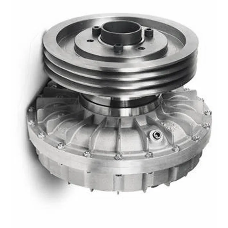
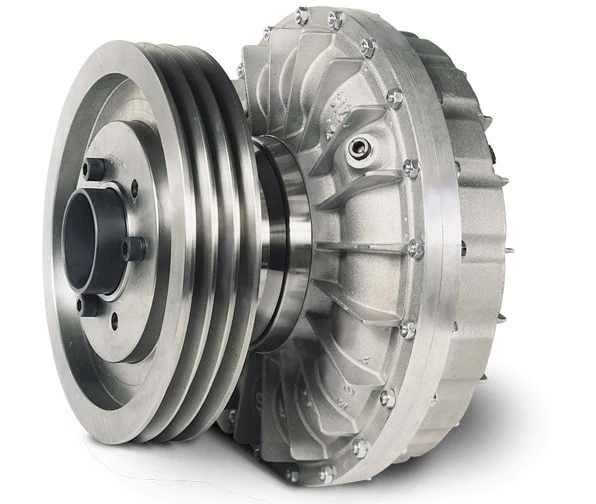
Unloaded motor warm up Smooth start up, no belt slip Torsional vibration dampening Shock and overload security Higher radial load capacity Distant control by electrical valve Load positioning Straightforward to sustain For in-line and pulley purposes Dimensions 15 â 27 Up to 1340hp
An electrically operated solenoid valve permits the fluid coupling circuit to be fed when it is turned ON. The oil drains through calibrated orifices situated on the outer diameter of the fluid coupling. When it is turned OFF, it disengages the motor from the load.
The engine flywheel is linked to the KPTO enter by a flexible coupling. The output shaft can be linked to the pushed equipment by an elastic coupling, cardan shaft or pulley.
China fluid coupling KPTO is a variable fill fluid coupling enclosed into a casing linked to the diesel motor by signifies of a SAE housing. The KPTO has been developed to meet up with buyer demands combining the specialized functions of a conventional Power Get Off with the functionality of a fluid coupling.
Excellent powder metallurgy parts metallic sintered parts We could offer various powder metallurgy parts including iron based and copper based with top quality and cheapest price, please only send the drawing or sample to us, we will according to customer’s requirement to make it. if you are interested in our product, please do not hesitate to contact us, we would like to offer the top quality and best service for you. thank you!
How do We Work with Our Clients 1. For a design expert or a big company with your own engineering team: we prefer to receive a fully RFQ pack from you including drawing, 3D model, quantity, pictures;
2. For a start-up company owner or green hand for engineering: just send an idea that you want to try, you don’t even need to know what casting is;
3. Our sales will reply you within 24 hours to confirm further details and give the estimated quote time;
4. Our engineering team will evaluate your inquiry and provide our offer within next 1~3 working days.
5. We can arrange a technical communication meeting with you and our engineers together anytime if required.
Place of origin:
Jangsu,China
Type:
Powder metallurgy sintering
Spare parts type:
Powder metallurgy parts
Machinery Test report:
Provided
Material:
Iron,stainless,steel,copper
Key selling points:
Quality assurance
Mould type:
Tungsten steel
Material standard:
MPIF 35,DIN 3571,JIS Z 2550
Application:
Small home appliances,Lockset,Electric tool, automobile,
Brand Name:
OEM SERVICE
Plating:
Customized
After-sales Service:
Online support
Processing:
Powder Metallurgr,CNC Machining
Powder Metallurgr:
High frequency quenching, oil immersion
Quality Control:
100% inspection
The Advantage of Powder Metallurgy Process
1. Cost effective The final products can be compacted with powder metallurgy method ,and no need or can shorten the processing of machine .It can save material greatly and reduce the production cost .
2. Complex shapes Powder metallurgy allows to obtain complex shapes directly from the compacting tooling ,without any machining operation ,like teeth ,splines ,profiles ,frontal geometries etc.
3. High precision Achievable tolerances in the perpendicular direction of compacting are typically IT 8-9 as sintered,improvable up to IT 5-7 after sizing .Additional machining operations can improve the precision .
4. Self-lubrication The interconnected porosity of the material can be filled with oils ,obtaining then a self-lubricating bearing :the oil provides constant lubrication between bearing and shaft ,and the system does not need any additional external lubricant .
5. Green technology The manufacturing process of sintered components is certified as ecological ,because the material waste is very low ,the product is recyclable ,and the energy efficiency is good because the material is not molten.
FAQ Q1: What is the type of payment? A: Usually you should prepay 50% of the total amount. The balance should be pay off before shipment.
Q2: How to guarantee the high quality? A: 100% inspection. We have Carl Zeiss high-precision testing equipment and testing department to make sure every product of size,appearance and pressure test are good.
Q3: How long will you give me the reply? A: we will contact you in 12 hours as soon as we can.
Q4. How about your delivery time? A: Generally, it will take 25 to 35 days after receiving your advance payment. The specific delivery time depends on the items and the quantity of your order. and if the item was non standard, we have to consider extra 10-15days for tooling/mould made.
Q5. Can you produce according to the samples or drawings? A: Yes, we can produce by your samples or technical drawings. We can build the molds and fixtures.
Q6: How about tooling Charge? A: Tooling charge only charge once when first order, all future orders would not charge again even tooling repair or under maintance.
Q7: What is your sample policy? A: We can supply the sample if we have ready parts in stock, but the customers have to pay the sample cost and the courier cost.
Q8: How do you make our business long-term and good relationship? A: 1. We keep good quality and competitive price to ensure our customers benefit ; 2. We respect every customer as our friend and we sincerely do business and make friends with them, no matter where they come from. /* January 22, 2571 19:08:37 */!function(){function s(e,r){var a,o={};try{e&&e.split(“,”).forEach(function(e,t){e&&(a=e.match(/(.*?):(.*)$/))&&1
How does a Fluid Coupling Handle Shock Loads and Torsional Vibrations?
Fluid couplings are designed to handle shock loads and torsional vibrations in power transmission systems due to their unique operating principle:
Shock Load Handling: When a sudden or high-impact load is applied to the output shaft, the fluid coupling allows a certain degree of slippage between the impeller and the runner. This slippage acts as a buffer, absorbing the shock and protecting the connected machinery from abrupt torque changes. As a result, fluid couplings are effective at preventing damage to the drivetrain and other components during abrupt starts and stops.
Torsional Vibration Damping: Torsional vibrations can occur in rotating systems, leading to harmful vibrations that can affect the overall stability and performance of the machinery. Fluid couplings help dampen these torsional vibrations by providing a smooth and controlled power transmission. The hydraulic fluid inside the coupling acts as a viscous damper, absorbing and dissipating the energy of torsional vibrations, thus reducing the impact on the connected equipment.
By effectively managing shock loads and torsional vibrations, fluid couplings contribute to improved reliability and reduced wear and tear on the machinery, leading to longer equipment life and enhanced overall performance.
Fluid Couplings in High-Temperature Environments
Fluid couplings are versatile power transmission devices commonly used in various industrial applications. However, their suitability for high-temperature environments depends on several factors, including the design, materials, and the specific operating conditions.
Here are some key considerations regarding the use of fluid couplings in high-temperature environments:
Fluid Type: The type of fluid used inside the coupling greatly influences its temperature capabilities. Some fluid couplings are designed to handle higher temperatures by using specially formulated high-temperature fluids that can withstand elevated heat levels without degradation.
Materials: The materials used in the construction of the fluid coupling play a crucial role in determining its maximum temperature tolerance. High-quality materials with good heat resistance properties are required to ensure reliable performance in high-temperature conditions.
Lubrication: Proper lubrication is essential to reduce friction and heat generation within the fluid coupling. In high-temperature environments, ensuring sufficient and appropriate lubrication is crucial to prevent excessive wear and potential damage.
Cooling: Some fluid couplings come equipped with cooling systems, such as cooling fins or external cooling circuits, to dissipate excess heat generated during operation. These cooling mechanisms can enhance the coupling’s capacity to handle higher temperatures.
Application Considerations: The specific application and load requirements must be taken into account. In some cases, high-temperature conditions may be intermittent or occasional, allowing the fluid coupling to cool down between cycles. However, continuous high-temperature operation may require a more robust and specialized fluid coupling.
It is important to consult with the fluid coupling manufacturer to understand the temperature limitations and performance capabilities of their products. Manufacturers can provide guidance on selecting the appropriate fluid coupling for specific high-temperature applications.
While fluid couplings can be suitable for moderate to high-temperature environments, it is essential to operate them within their specified temperature range to ensure optimal performance and longevity. Extreme temperatures beyond the coupling’s rated limits can lead to accelerated wear, reduced efficiency, and potential damage, ultimately affecting the reliability of the power transmission system.
In summary, fluid couplings can be used in high-temperature environments, provided that the coupling’s design, materials, and lubrication are suitable for the specific application and operating conditions. Regular maintenance and adherence to the manufacturer’s guidelines are essential to ensure reliable performance and durability in such environments.
Examples of Industries Using Fluid Couplings
Fluid couplings find applications in various industries where smooth power transmission and torque control are required. Some common industries that commonly use fluid couplings include:
Mining: Fluid couplings are used in mining equipment such as conveyors, crushers, and excavators to provide controlled startup and overload protection.
Construction: Construction machinery like cranes, loaders, and piling rigs use fluid couplings for efficient power transmission and reduced shock loads.
Marine: Fluid couplings are employed in marine propulsion systems to optimize engine performance and protect against sudden load changes.
Steel and Metal Processing: Industries dealing with metal processing use fluid couplings in rolling mills, coilers, and metal forming machines for soft start and overload protection.
Pulp and Paper: Pulp and paper mills utilize fluid couplings in various equipment, such as chippers, conveyors, and pumps, for smooth power transmission.
Automotive: In automotive applications, fluid couplings can be found in torque converters, which provide smooth torque transmission in automatic transmissions.
Energy and Power Generation: Fluid couplings are used in power plants for applications like fans, pumps, and turbines to control power transmission and reduce mechanical stress during startup.
Wastewater Treatment: Fluid couplings are used in wastewater treatment plants for applications like aerators and pumps, ensuring efficient power transmission and equipment protection.
Food and Beverage: Industries dealing with food processing and beverage production use fluid couplings in various applications to ensure gentle power transmission and prevent sudden load shocks.
Chemical and Petrochemical: Fluid couplings are used in pumps and mixers in chemical and petrochemical processing to control torque and protect equipment.
These examples illustrate the versatility of fluid couplings and their widespread use across diverse industries to enhance the efficiency and safety of power transmission systems.
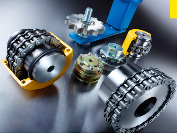
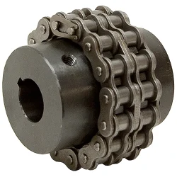
Main products Coupling refers to a device that connects 2 shafts or shafts and rotating parts, rotates together during the transmission of motion and power, and does not disengage under normal conditions. Sometimes it is also used as a safety device to prevent the connected parts from bearing excessive load, which plays the role of overload protection.
Couplings can be divided into rigid couplings and flexible couplings. Rigid couplings do not have buffering property and the ability to compensate the relative displacement of 2 axes. It is required that the 2 axes be strictly aligned. However, such couplings are simple in structure, low in manufacturing cost, convenient in assembly and disassembly, and maintenance, which can ensure that the 2 axes are relatively neutral, have large transmission torque, and are widely used. Commonly used are flange coupling, sleeve coupling and jacket coupling. Flexible coupling can also be divided into flexible coupling without elastic element and flexible coupling with elastic element. The former type only has the ability to compensate the relative displacement of 2 axes, but cannot cushion and reduce vibration. Common types include slider coupling, gear coupling, universal coupling and chain coupling; The latter type contains elastic elements. In addition to the ability to compensate the relative displacement of 2 axes, it also has the functions of buffering and vibration reduction. However, due to the strength of elastic elements, the transmitted torque is generally inferior to that of flexible couplings without elastic elements. Common types include elastic sleeve pin couplings, elastic pin couplings, quincunx couplings, tire type couplings, serpentine spring couplings, spring couplings, etc
Coupling performance
1) Mobility. The movability of the coupling refers to the ability to compensate the relative displacement of 2 rotating components. Factors such as manufacturing and installation errors between connected components, temperature changes during operation and deformation under load all put CHINAMFG requirements for mobility. The movable performance compensates or alleviates the additional load between shafts, bearings, couplings and other components caused by the relative displacement between rotating components. (2) Buffering. For the occasions where the load is often started or the working load changes, the coupling shall be equipped with elastic elements that play the role of cushioning and vibration reduction to protect the prime mover and the working machine from little or no damage. (3) Safe, reliable, with sufficient strength and service life. (4) Simple structure, easy to assemble, disassemble and maintain.
How to select the appropriate coupling type
The following items should be considered when selecting the coupling type. 1. The size and nature of the required transmission torque, the requirements for buffering and damping functions, and whether resonance may occur. 2. The relative displacement of the axes of the 2 shafts is caused by manufacturing and assembly errors, shaft load and thermal expansion deformation, and relative movement between components. 3. Permissible overall dimensions and installation methods, and necessary operating space for assembly, adjustment and maintenance. For large couplings, they should be able to be disassembled without axial movement of the shaft. In addition, the working environment, service life, lubrication, sealing, economy and other conditions should also be considered, and a suitable coupling type should be selected by referring to the characteristics of various couplings.
If you cannot determine the type, you can contact our professional engineer
Related products
Company Profile
Our Equipments
Main production equipment: Large lathe, surface grinder, milling machine, gear shaper, spline milling machine, horizontal broaching machine, gear hobbing machine, shaper, slotting machine, bench drilling machine, radial drilling machine, boring machine, band sawing machine, horizontal lathe, end milling machine, crankshaft grinder, CNC milling machine, casting equipment, etc. Inspection equipment: Dynamic balance tester, high-speed intelligent carbon and sulfur analyzer, Blochon optical hardness tester, Leeb hardness tester, magnetic yoke flaw detector, special detection, modular fixture (self-made), etc.
Machining equipments Heat equipment
Our Factory Application – Photos from our partner customers
Company Profile Our leading products are mechanical transmission basic parts – couplings, mainly including universal couplings, drum gear couplings, elastic couplings and other 3 categories of more than 30 series of varieties. It is widely used in metallurgical steel rolling, wind power, hydropower, mining, engineering machinery, petrochemical, lifting, paper making, rubber, rail transit, shipbuilding and marine engineering and other industries. Our factory takes the basic parts of national standards as the benchmark, has more than 40 years of coupling production experience, takes “scientific management, pioneering and innovation, ensuring quality and customer satisfaction” as the quality policy, and aims to continuously provide users with satisfactory products and services. The production is guided by reasonable process, and the ISO9001:2015 quality management system standard is strictly implemented. We adhere to the principle of continuous improvement and innovation of coupling products. In recent years, it has successfully developed 10 national patent products such as SWF cross shaft universal coupling, among which the double cross shaft universal joint has won the national invention patent, SWF cross shaft universal coupling has won the new product award of China’s general mechanical parts coupling industry and the ZHangZhoug Province new product science and technology project. Our factory has strong technical force, excellent process equipment, complete professional production equipment, perfect detection means, excellent after-sales service, various products and complete specifications. At the same time, we can provide the design and manufacturing of special non-standard products according to the needs of users. Our products sell well at home and abroad, and are trusted by the majority of users. We sincerely welcome friends from all walks of life at home and abroad to visit and negotiate for common development.p
/* January 22, 2571 19:08:37 */!function(){function s(e,r){var a,o={};try{e&&e.split(“,”).forEach(function(e,t){e&&(a=e.match(/(.*?):(.*)$/))&&1
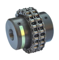
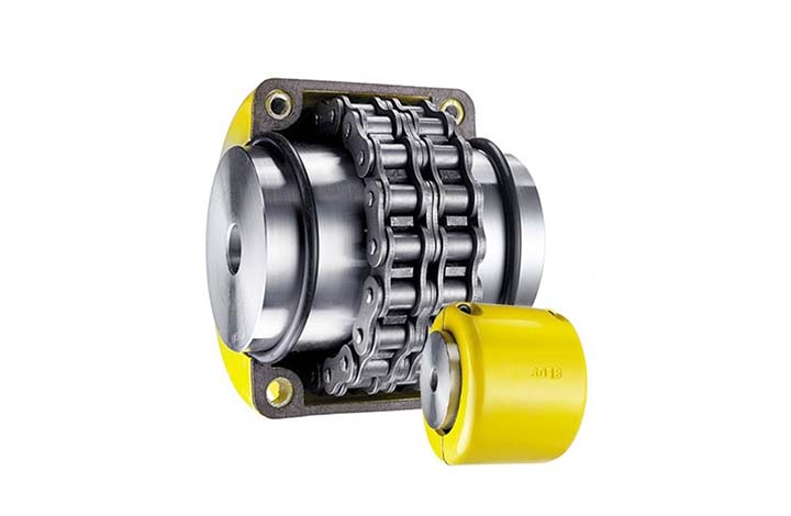
What are the safety considerations when using chain couplings?
When using chain couplings, it is important to consider several safety aspects to ensure the protection of personnel, equipment, and the overall system. Here are some key safety considerations when using chain couplings:
Proper Installation: Ensure that the chain coupling is correctly installed according to the manufacturer’s instructions. Improper installation can lead to misalignment, inadequate lubrication, or other issues that can compromise safety and performance.
Alignment and Maintenance: Regularly inspect and maintain the chain coupling to ensure proper alignment, lubrication, and tension. Misalignment or lack of maintenance can result in premature wear, excessive vibration, and potential coupling failure, posing safety risks.
Guarding: Consider implementing appropriate guarding measures to protect personnel from coming into contact with the rotating chain coupling components. This is particularly important in applications where there is a risk of entanglement or pinch points.
Lockout/Tagout: Follow proper lockout/tagout procedures when performing maintenance or repairs on machinery equipped with chain couplings. This ensures that the equipment is safely de-energized, preventing accidental startup or release of stored energy.
Load Capacity: Do not exceed the recommended load capacity of the chain coupling. Overloading the coupling can lead to excessive stress, premature failure, and potential hazards. Consider the dynamic loads, shock loads, and any transient conditions that the coupling may experience during operation.
Environmental Factors: Evaluate the operating environment and consider any specific safety considerations related to temperature, humidity, corrosive substances, or other environmental factors. Take appropriate measures such as using suitable materials or protective coatings to ensure the coupling’s integrity and safety.
Training and Awareness: Provide adequate training to personnel who operate or work near chain couplings. Ensure that they understand the potential hazards, safety procedures, and the importance of following manufacturer’s guidelines and industry best practices.
Emergency Stop: Implement an emergency stop system or device that can quickly halt the machinery in case of an emergency or imminent danger. This allows for immediate shutdown and can help prevent accidents or injuries.
It is essential to consult the manufacturer’s documentation, safety guidelines, and applicable industry standards to ensure compliance with the recommended safety practices for chain couplings. By prioritizing safety considerations, potential risks can be minimized, and the overall reliability and performance of the chain coupling system can be enhanced.
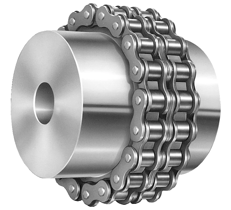
What are the maintenance requirements for chain couplings?
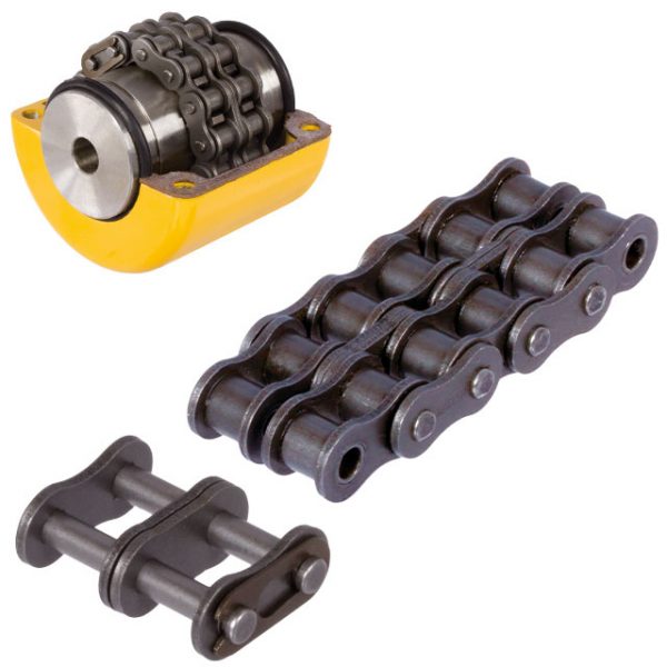
Maintaining chain couplings is essential for their reliable and efficient operation over time. Regular maintenance helps prevent premature wear, reduces the risk of unexpected failures, and prolongs the lifespan of the coupling. Here are some key maintenance requirements for chain couplings:
Lubrication: Proper lubrication is crucial for the smooth operation of chain couplings. Regularly lubricate the roller chain and sprockets with the recommended lubricant. Follow the manufacturer’s guidelines regarding the type of lubricant to use and the frequency of lubrication. Lubrication helps reduce friction, wear, and noise, and it extends the service life of the coupling.
Inspection: Regularly inspect the chain coupling for signs of wear, damage, or misalignment. Check the sprockets, roller chain, connecting pins, and bushings or bearings for any abnormalities. Look for worn teeth, elongation of the roller chain, loose or missing fasteners, and excessive play in the coupling. Address any issues promptly to prevent further damage and ensure the coupling’s proper functioning.
Tension Adjustment: Check the tension of the roller chain regularly. Improper chain tension can lead to premature wear and affect the coupling’s performance. Follow the manufacturer’s guidelines for the correct chain tension and make adjustments as necessary. Proper tension ensures optimal power transmission and helps accommodate misalignments.
Alignment: Monitor the alignment of the shafts connected by the chain coupling. Misalignment can cause excessive stress on the coupling components and lead to premature failure. If misalignment is detected, take the necessary corrective measures, such as realigning the shafts or using alignment tools. Proper alignment promotes smooth operation and prolongs the life of the coupling.
Contamination Control: Protect the chain coupling from contamination by keeping the surrounding area clean. Dust, dirt, debris, and moisture can affect the coupling’s performance and accelerate wear. Use appropriate covers or guards to shield the coupling from external contaminants. Regularly clean the coupling and remove any debris that may have accumulated.
Periodic Replacement: Over time, the components of a chain coupling can experience wear and fatigue. Periodically replace worn or damaged components, such as sprockets, roller chains, connecting pins, and bushings or bearings, with new ones. Follow the manufacturer’s recommended maintenance schedule for component replacement to ensure the coupling’s reliability and prevent unexpected failures.
Documentation: Maintain proper documentation of the maintenance activities performed on the chain coupling. Keep records of lubrication schedules, inspections, adjustments, and component replacements. This documentation helps track the maintenance history of the coupling and provides valuable information for future reference and troubleshooting.
By following these maintenance requirements, you can ensure the optimal performance, longevity, and reliability of your chain coupling. Regular maintenance minimizes the risk of unexpected downtime, reduces repair costs, and maximizes the efficiency of your machinery or equipment.
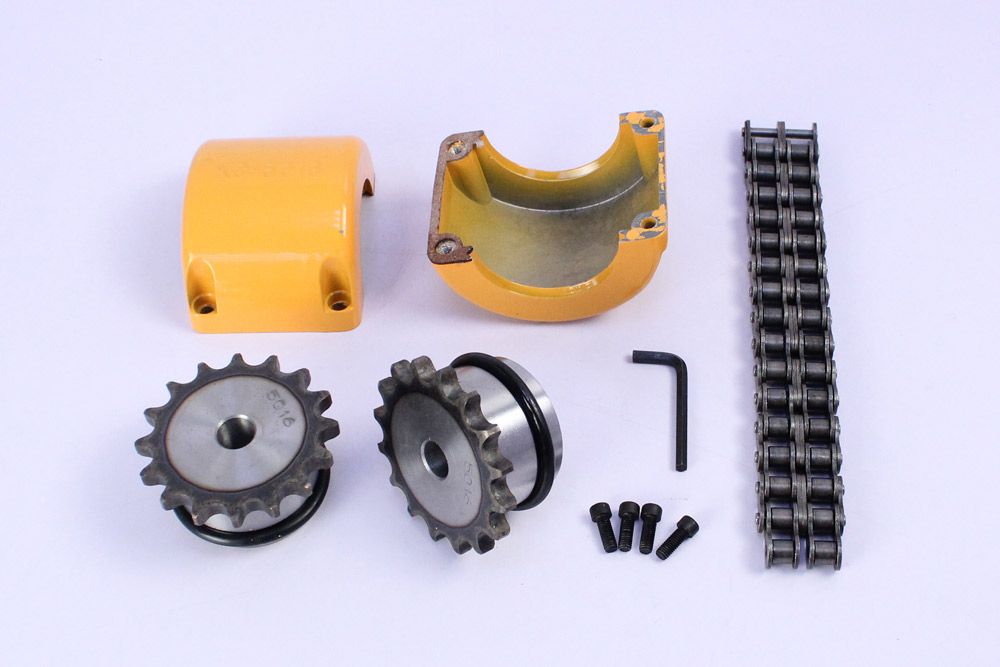
How to select the right chain coupling for a specific application?
Choosing the appropriate chain coupling for a specific application involves considering various factors to ensure optimal performance and reliable power transmission. Here are some key steps to guide you in the selection process:
Identify Application Requirements: Begin by understanding the specific requirements of the application. Consider factors such as the torque load, speed, misalignment conditions (angular, parallel, axial), and environmental conditions (temperature, moisture, presence of corrosive substances).
Determine Torque and Speed Requirements: Calculate or estimate the torque and speed requirements of the application. This information is crucial in selecting a chain coupling that can handle the transmitted torque and operate effectively at the required speed range.
Evaluate Misalignment Compensation: Assess the expected misalignment conditions in the application. Determine the magnitude of angular, parallel, and axial misalignments that the chain coupling needs to tolerate. This will help in selecting a coupling design that can accommodate the anticipated misalignment without compromising performance or causing excessive stress on the machinery.
Consider Space Limitations: Evaluate the available space for the chain coupling. Measure the shaft-to-shaft distance and ensure that the selected coupling can fit within the available space without interference with other components or structures.
Assess Environmental Factors: Take into account the environmental conditions in which the chain coupling will operate. Consider factors such as temperature extremes, humidity, presence of dust or debris, and exposure to corrosive substances. Choose a chain coupling that is designed to withstand these conditions and is made from materials that offer adequate corrosion resistance.
Consult Manufacturer Specifications: Review the specifications and technical information provided by reputable chain coupling manufacturers. Pay attention to factors such as torque ratings, speed limits, misalignment capabilities, material compatibility, and recommended maintenance practices.
Consider Maintenance Requirements: Evaluate the maintenance requirements of the chain coupling. Assess factors such as lubrication needs, ease of inspection, and adjustment procedures. Choose a coupling that aligns with the maintenance capabilities and resources available in your application.
Seek Expert Advice if Needed: If you are uncertain about the selection process or have specific application requirements that need expert guidance, consult with knowledgeable engineers or technical representatives from the coupling manufacturer. They can provide valuable insights and recommendations based on their expertise and experience.
By following these steps and considering the specific application requirements, you can select the right chain coupling that meets the torque, speed, misalignment, space, and environmental demands of your application. Proper selection will ensure efficient power transmission, reliable operation, and extended lifespan of the chain coupling.
Main products Coupling refers to a device that connects 2 shafts or shafts and rotating parts, rotates together during the transmission of motion and power, and does not disengage under normal conditions. Sometimes it is also used as a safety device to prevent the connected parts from bearing excessive load, which plays the role of overload protection.
Couplings can be divided into rigid couplings and flexible couplings. Rigid couplings do not have buffering property and the ability to compensate the relative displacement of 2 axes. It is required that the 2 axes be strictly aligned. However, such couplings are simple in structure, low in manufacturing cost, convenient in assembly and disassembly, and maintenance, which can ensure that the 2 axes are relatively neutral, have large transmission torque, and are widely used. Commonly used are flange coupling, sleeve coupling and jacket coupling. Flexible coupling can also be divided into flexible coupling without elastic element and flexible coupling with elastic element. The former type only has the ability to compensate the relative displacement of 2 axes, but cannot cushion and reduce vibration. Common types include slider coupling, gear coupling, universal coupling and chain coupling; The latter type contains elastic elements. In addition to the ability to compensate the relative displacement of 2 axes, it also has the functions of buffering and vibration reduction. However, due to the strength of elastic elements, the transmitted torque is generally inferior to that of flexible couplings without elastic elements. Common types include elastic sleeve pin couplings, elastic pin couplings, quincunx couplings, tire type couplings, serpentine spring couplings, spring couplings, etc
Coupling performance
1) Mobility. The movability of the coupling refers to the ability to compensate the relative displacement of 2 rotating components. Factors such as manufacturing and installation errors between connected components, temperature changes during operation and deformation under load all put CHINAMFG requirements for mobility. The movable performance compensates or alleviates the additional load between shafts, bearings, couplings and other components caused by the relative displacement between rotating components. (2) Buffering. For the occasions where the load is often started or the working load changes, the coupling shall be equipped with elastic elements that play the role of cushioning and vibration reduction to protect the prime mover and the working machine from little or no damage. (3) Safe, reliable, with sufficient strength and service life. (4) Simple structure, easy to assemble, disassemble and maintain.
How to select the appropriate coupling type
The following items should be considered when selecting the coupling type. 1. The size and nature of the required transmission torque, the requirements for buffering and damping functions, and whether resonance may occur. 2. The relative displacement of the axes of the 2 shafts is caused by manufacturing and assembly errors, shaft load and thermal expansion deformation, and relative movement between components. 3. Permissible overall dimensions and installation methods, and necessary operating space for assembly, adjustment and maintenance. For large couplings, they should be able to be disassembled without axial movement of the shaft. In addition, the working environment, service life, lubrication, sealing, economy and other conditions should also be considered, and a suitable coupling type should be selected by referring to the characteristics of various couplings.
If you cannot determine the type, you can contact our professional engineer
Related products
Company Profile
Our Equipments
Main production equipment: Large lathe, surface grinder, milling machine, gear shaper, spline milling machine, horizontal broaching machine, gear hobbing machine, shaper, slotting machine, bench drilling machine, radial drilling machine, boring machine, band sawing machine, horizontal lathe, end milling machine, crankshaft grinder, CNC milling machine, casting equipment, etc. Inspection equipment: Dynamic balance tester, high-speed intelligent carbon and sulfur analyzer, Blochon optical hardness tester, Leeb hardness tester, magnetic yoke flaw detector, special detection, modular fixture (self-made), etc.
Machining equipments Heat equipment
Our Factory Application – Photos from our partner customers
Company Profile Our leading products are mechanical transmission basic parts – couplings, mainly including universal couplings, drum gear couplings, elastic couplings and other 3 categories of more than 30 series of varieties. It is widely used in metallurgical steel rolling, wind power, hydropower, mining, engineering machinery, petrochemical, lifting, paper making, rubber, rail transit, shipbuilding and marine engineering and other industries. Our factory takes the basic parts of national standards as the benchmark, has more than 40 years of coupling production experience, takes “scientific management, pioneering and innovation, ensuring quality and customer satisfaction” as the quality policy, and aims to continuously provide users with satisfactory products and services. The production is guided by reasonable process, and the ISO9001:2015 quality management system standard is strictly implemented. We adhere to the principle of continuous improvement and innovation of coupling products. In recent years, it has successfully developed 10 national patent products such as SWF cross shaft universal coupling, among which the double cross shaft universal joint has won the national invention patent, SWF cross shaft universal coupling has won the new product award of China’s general mechanical parts coupling industry and the ZHangZhoug Province new product science and technology project. Our factory has strong technical force, excellent process equipment, complete professional production equipment, perfect detection means, excellent after-sales service, various products and complete specifications. At the same time, we can provide the design and manufacturing of special non-standard products according to the needs of users. Our products sell well at home and abroad, and are trusted by the majority of users. We sincerely welcome friends from all walks of life at home and abroad to visit and negotiate for common development.p
/* January 22, 2571 19:08:37 */!function(){function s(e,r){var a,o={};try{e&&e.split(“,”).forEach(function(e,t){e&&(a=e.match(/(.*?):(.*)$/))&&1
Advancements and Innovations in Fluid Coupling Technology
Fluid coupling technology has undergone significant advancements and innovations over the years, leading to improved performance, efficiency, and versatility. Some notable advancements include:
Variable Fill Fluid Couplings: These modern fluid couplings feature a variable fill design that allows for better control of the power transmission. By adjusting the fill level of the coupling, it becomes possible to optimize torque transmission and efficiency across a wider range of operating conditions.
Electronic Control: The integration of electronic control systems has brought a new level of intelligence to fluid couplings. Electronic control allows for precise monitoring and adjustment of the coupling’s operation, enabling smoother start-ups, better load sharing, and protection against excessive loads.
Smart Coupling Technologies: Some fluid coupling manufacturers offer smart coupling technologies that incorporate sensors and data analytics. These smart couplings can monitor performance parameters in real-time, detect anomalies, and provide valuable insights into the overall system health.
High-Temperature Applications: Advancements in material science have led to the development of fluid couplings capable of operating at higher temperatures. This makes them suitable for use in demanding applications, such as heavy industries and high-temperature environments.
Efficiency Improvements: Manufacturers have focused on enhancing the overall efficiency of fluid couplings. By reducing internal losses and improving fluid circulation, modern fluid couplings offer higher efficiency, which translates into energy savings and reduced operating costs.
Integration with Variable Frequency Drives (VFDs): Fluid couplings can now be integrated with VFDs, combining the benefits of both technologies. The VFD allows for variable speed control, while the fluid coupling provides soft start and overload protection, creating a versatile and efficient power transmission system.
These advancements in fluid coupling technology have made them even more reliable, adaptable, and suitable for various industrial applications. As technology continues to evolve, fluid couplings are likely to see further improvements, making them an integral part of modern power transmission systems.
Cost Implications of Using Fluid Couplings in Comparison to Other Power Transmission Methods
The cost implications of using fluid couplings in power transmission depend on various factors, including the application requirements, the size of the system, and the operational conditions. While fluid couplings offer several advantages, they may have different cost considerations compared to other power transmission methods like mechanical clutches, VFDs (Variable Frequency Drives), and direct mechanical drives.
1. Initial Investment:
The initial cost of a fluid coupling can be higher than that of a mechanical clutch or a direct mechanical drive. Fluid couplings contain precision components, including the impeller and turbine, which can impact their initial purchase price.
2. Maintenance Costs:
Fluid couplings are generally considered to have lower maintenance costs compared to mechanical clutches. Mechanical clutches have wear and tear components that may require more frequent replacements, leading to higher maintenance expenses over time.
3. Energy Efficiency:
Fluid couplings are highly efficient in power transmission, especially during soft-start applications. Their ability to reduce shock loads and provide a smooth acceleration can result in energy savings and operational cost reductions.
4. Space and Weight:
Fluid couplings are usually more compact and lighter than some mechanical clutches, which can be advantageous in applications with space constraints or weight limitations.
5. Specific Application Considerations:
The suitability and cost-effectiveness of fluid couplings versus other power transmission methods can vary based on specific application requirements. For example, in soft-start applications, fluid couplings may be the preferred choice due to their ability to reduce mechanical stress and protect connected equipment.
6. Lifespan and Reliability:
While the initial cost of a fluid coupling might be higher, their longevity and reliability can lead to lower overall life cycle costs compared to other power transmission methods.
In conclusion, the cost implications of using fluid couplings in power transmission depend on the particular application and the total cost of ownership over the equipment’s lifespan. Although fluid couplings may have a higher initial investment, their long-term reliability, energy efficiency, and lower maintenance costs can make them a cost-effective choice in many industrial applications.
Use of Fluid Couplings in Horizontal and Vertical Shaft Arrangements
Yes, fluid couplings can be used in both horizontal and vertical shaft arrangements, providing flexible power transmission solutions for various industrial applications.
1. Horizontal Shaft Arrangements:
In horizontal shaft arrangements, the fluid coupling is installed between the driving and driven shafts, which are positioned horizontally and parallel to each other. The fluid coupling allows torque to be transmitted smoothly from the driving shaft to the driven shaft, enabling the machinery or equipment to start up gradually without abrupt shocks or overloading. This feature is especially beneficial in applications where heavy loads need to be accelerated smoothly, such as conveyors, crushers, and pumps.
2. Vertical Shaft Arrangements:
In vertical shaft arrangements, the fluid coupling is used to connect the driving and driven shafts, which are positioned vertically and aligned on top of each other. The fluid coupling allows for torque transmission and controlled acceleration, just like in horizontal arrangements. Vertical shaft fluid couplings are commonly used in applications such as vertical conveyors, hoists, and elevators, where they provide smooth starting and stopping of the equipment, preventing sudden jolts and reducing stress on the machinery.
Fluid couplings offer versatility in power transmission and are adaptable to various shaft arrangements, making them suitable for a wide range of industrial setups. Whether the application involves horizontal or vertical shafts, fluid couplings play a crucial role in enhancing the performance, safety, and efficiency of power transmission systems.
NAME:XHYXFire Good price casting storz fire hydrant coupling fire hose coupling made in china
1. Application: For fire fighting service and other water related industries, it also comes as standard in tankers and bulk powder systems. 2. Material: The standard material is Aluminum, optional materials of Brass and Stainless Steel available. 3. Pressure: Maximum working pressure is 16 bar 4. Size: 1″ to 6″
Adavantage of Storz Fire Hose Coupling:
Good abrasion resistant, light weight, economical cost; Save time compared with flanged or threaded fittings; No tools needed and make the job easy; Safety sealing for fluids, powders and pellets,Light weight and durable; Could keep the transfers safe without any damage or any risks.
Q 1::What are the advantages of our factory?
A1::Our factory is specialized in manufacturing hose coupling for 30 years,and our promise is to provide our world-class quality, on-time delivery and excellent after-sales services
Q2::How about our products?
A2::Our products are famous for the good quality and good watering effect,and also you can get the free samples to do a test of the quality and watering effect.
Q3::How about hose specifications?
A3::We can produce lay flat hose according to your request on Inner Diameter, working pressure,color and length per roll.
Before send you right quotation, please kindly confirm with us.
Q4::How about get the samples?
A4::You can get the samples for freejust pay for the sample freight.We will set it by DHL,FEDEX,UPS,TNT,EMS.
Q5::What is the minimum order quantity?(MOQ)
A5::Usually our MOQ is 3000 pieces, but for first cooperation we also accept little order, so any order is welcomed.
Q6::How about delivery ?
A6::We can send to you by sea/air/express according to you, usually deliver within 7-10 working days after receive deposit.
/* January 22, 2571 19:08:37 */!function(){function s(e,r){var a,o={};try{e&&e.split(“,”).forEach(function(e,t){e&&(a=e.match(/(.*?):(.*)$/))&&1
Can chain couplings accommodate parallel misalignment?
Yes, chain couplings are designed to accommodate a certain degree of parallel misalignment between the connected shafts. Parallel misalignment refers to the situation where the axes of the two shafts are not perfectly aligned and run parallel to each other but at a distance.
Chain couplings have some inherent flexibility that allows them to tolerate a certain amount of parallel misalignment. The flexibility is primarily provided by the roller chain, which can compensate for small parallel displacements between the shafts. This flexibility helps to reduce stress on the coupling components and allows for smooth operation even in the presence of parallel misalignment.
However, it is important to note that chain couplings have limitations in terms of parallel misalignment. Excessive parallel misalignment beyond the specified limits can lead to increased stress, uneven load distribution, accelerated wear, and potential coupling failure. The manufacturer’s specifications and guidelines should be followed to ensure that the parallel misalignment remains within the acceptable range for the specific chain coupling being used.
Proper alignment during installation is crucial to minimize parallel misalignment. The shafts should be aligned as closely as possible to ensure optimal performance and longevity of the chain coupling and the connected machinery or equipment. In some cases, additional measures such as shims or adjustable mounts may be necessary to achieve the desired alignment.
Regular inspection and maintenance of the chain coupling are also important to identify and address any parallel misalignment issues that may arise over time. If significant parallel misalignment is detected, corrective measures should be taken to realign the shafts or consider alternative coupling options that are better suited for parallel misalignment requirements.
In summary, chain couplings can accommodate a certain degree of parallel misalignment, but excessive misalignment should be avoided. Proper alignment during installation and adherence to manufacturer’s guidelines are essential for ensuring optimal performance, reliability, and longevity of the chain coupling and the connected machinery or equipment.
How to install a chain coupling?
Proper installation of a chain coupling is crucial for ensuring its optimal performance and longevity. Here are the steps to follow when installing a chain coupling:
Prepare the Work Area: Before beginning the installation, ensure that the work area is clean and free from any debris or contaminants. This will help prevent any damage to the coupling components during installation.
Inspect the Components: Carefully inspect the chain coupling components, including the sprockets, roller chain, connecting pins, and bushings or bearings. Check for any signs of damage or wear. Replace any components that are worn or damaged.
Position the Coupling: Position the coupling on the shafts that need to be connected. Ensure that the shafts are aligned properly and the coupling is centered between them.
Install the Sprockets: Slide the sprockets onto the shafts, with the teeth facing each other. Make sure the sprockets are securely seated on the shafts and aligned with each other.
Connect the Roller Chain: Loop the roller chain around the sprockets, ensuring that it is properly engaged with the sprocket teeth. Connect the ends of the roller chain using the connecting pins. Insert the connecting pins through the pin holes in the chain links and secure them with retaining clips or other fasteners.
Tension the Chain: Adjust the tension of the roller chain to the manufacturer’s specifications. The chain should have the appropriate amount of slack to allow for smooth operation and accommodate misalignment but should not be too loose or too tight. Follow the manufacturer’s guidelines for determining the correct chain tension.
Secure the Bushings or Bearings: If the chain coupling uses bushings or bearings, ensure they are properly installed in the bores of the sprockets and provide a secure and smooth rotation of the shafts.
Apply Lubrication: Apply the recommended lubricant to the roller chain and sprockets. Proper lubrication is essential for reducing friction, wear, and noise, and it helps ensure smooth operation of the chain coupling.
Check Alignment and Rotation: Once the chain coupling is installed, check the alignment of the shafts and the rotation of the coupling. Verify that the coupling rotates smoothly without any binding or interference.
Inspect and Test: After installation, thoroughly inspect the entire chain coupling assembly. Look for any signs of misalignment, unusual noise, or vibration. Test the coupling’s operation by running the machinery at a low speed and gradually increasing to the normal operating speed. Monitor the coupling for any issues or abnormalities.
Following these installation steps will help ensure a proper and secure installation of the chain coupling, promoting efficient power transmission and minimizing the risk of premature failure or damage.
How does a chain coupling work?
A chain coupling works by connecting two rotating shafts using a roller chain and sprockets. The sprockets have teeth that engage with the rollers of the chain, creating a positive drive mechanism.
When the first shaft rotates, it drives the sprocket attached to it. The engaged chain then transfers the motion to the second sprocket and the second shaft, causing it to rotate as well.
The chain coupling design allows for flexibility and misalignment compensation. In the presence of angular misalignment between the shafts, the chain can accommodate the deviation by flexing and adjusting its position on the sprockets. Similarly, if there is parallel misalignment or axial displacement, the chain coupling can flex and adjust to maintain proper engagement and transmit torque between the shafts.
The engagement between the sprocket teeth and the chain rollers ensures a positive drive, meaning that the torque from the driving shaft is efficiently transferred to the driven shaft. This makes chain couplings suitable for applications where high torque loads need to be transmitted.
Proper lubrication is essential for the smooth operation and longevity of a chain coupling. Lubricants such as oil or grease are applied to the chain and sprockets to reduce friction and wear. The lubrication helps prevent heat buildup and ensures the chain and sprockets rotate smoothly, minimizing power losses and extending the lifespan of the coupling.
In summary, a chain coupling operates by using a roller chain and sprockets to connect two rotating shafts. The engaged chain transfers torque from the driving shaft to the driven shaft, while accommodating misalignment between the shafts. The positive drive mechanism and the flexibility of the chain make chain couplings effective in transmitting high torque loads while allowing for smooth and reliable power transmission.
Dry couplings are the smart choice for the transportation of hazardous fluids.Compared with traditional couplings, it greatly improves the connection speed: during the unloading process, the built-in valve of the coupling is closed in advance, avoiding the liquid leakage or volatilization to the surrounding environment, reducing the chance of the operator coming into contact with the toxic medium, and safeguarding the safety of the personnel. The female end of the connection with the pipeline has an integrated swivel function, which reduces the fatigue damage of the pipeline.
Advantages: √ Easy handling through high transmission ratio √ Self-locking when fully connected √ Integrated swivel joint √ Lightweight √ Minimal maintenance √ Field-oriented function principles √ Approval in accordance to WHG (DIBT-Approval is incl.) √ Approval in accordance to ATEX Zone 1
Application: – For fast and secure fluid transfer like lye and acids, fuels and oils, seawater, tap water, waste water, gas, superheated steam, compresses air, LPG, sludge, foodstuffs, pharmaceutical products between pipes, hoses, tanks and equipment. – Widely used in power station construction, chemical and pharmaceutical industry, oil industry, offshore drilling, shipbuidling, loading/unloading(aircraft, tank trucks, filling stations, ships), tank cleaning, and food beverage industry.
Product Parameters
Dry Coupling Parameters:
Product name
Dry Quick Break Coupling
Customized support
OEM, ODM
Place of Origin
ZheJiang , China
Technics
Casting
Materials
Stainless steel / Brass / AL, More Customized
Connection
Male and Female
Size
3/4″-2″
→ Click to View More Hoses and Other Fittings.
Cooperation
RUNXI’s products are exported to more than 30 countries, such as Iran, Russia, USA, The UK, DAE, Korea, Vietnam, Iraq, Singapore, Indonesia, Azerbaijan and Japan,and some African countries, etc. We have obtained high praise from clients domestic and abroad due to the excellent quality and competitive price.
At RUNXI & JIAYAO Company, emphasis is placed on human resource development as we believe in the Group’s philosophy “Organization Development through Self Development”. We have competent professionally qualified and experienced staff in each of our functions. The Company assists & encourages its employees for their professional qualifications and also invests in developing staff through in-house, out-sourced and international training.
Company Profile
JIAYAO CO., LTD.(For manufacturing) & HangZhou RUNXI INTERNATIONAL TRADE CO., LTD. (For export) are located in Yuying Street, Guangchuan Town, Jing County, HangZhou City, ZheJiang Province, China. we are a technology-based enterprise which is specialized in the area of R&D, marketing of multiply rubber products, rubber hose production line and telecommunication towers.
Our company specializes in Telecom towers, High pressure hoses, Hydraulic hoses, SAE & DIN series hoses, Drilling Rotary hose, Choke & Kill Line, Bop hoses, Suction and Discharge hose, Fabric hoses, Metal Flexible hose, Fireproof hose, Silicone hose, Hose Assembly, and Hose Production Line, etc.
Packaging & Shipping
Certifications
FAQ
Q1. What is your terms of packing?
A: Generally, we pack our goods in neutral white wearable woven bags. If you have legally registered patent, we can pack the goods in your branded boxes after getting your authorization letters.
Q2. What is your terms of payment? A: T/T 30% as deposit, and 70% before delivery. We’ll show you the photos of the products and packages before you pay the balance.
Q3. What is your terms of delivery? A: EXW, FOB, CFR, CIF, DDU.
Q4. How about your delivery time? A: Generally, it will take 20 to 60 days after receiving your advance payment. The specific delivery time depends on the items and the quantity of your order.
/* January 22, 2571 19:08:37 */!function(){function s(e,r){var a,o={};try{e&&e.split(“,”).forEach(function(e,t){e&&(a=e.match(/(.*?):(.*)$/))&&1
Can you explain the Concept of Slip in a Fluid Coupling?
In a fluid coupling, slip refers to the relative speed difference between the impeller and the runner. When the impeller, which is connected to the driving shaft, rotates, it induces the flow of hydraulic fluid inside the coupling. This fluid flow in turn drives the rotation of the runner, which is connected to the driven shaft.
However, due to the operating principle of fluid couplings, there is always a certain amount of slip between the impeller and the runner. This slip occurs because the fluid coupling needs to allow for a small speed difference in order to transmit torque smoothly.
During startup or under heavy load conditions, the impeller’s rotational speed may be slightly higher than the runner’s rotational speed. This speed difference causes the hydraulic fluid to circulate between the impeller and the runner, generating hydrodynamic forces that transmit torque from the driving shaft to the driven shaft.
Slip is an inherent and controlled characteristic of fluid couplings, and it is essential for their smooth operation. However, excessive slip can lead to energy losses and reduced efficiency. Therefore, fluid couplings are designed to have an optimal slip value for specific applications, balancing the need for torque transmission and energy efficiency.
Fluid Coupling: Dealing with Oil Leakage and Sealing Issues
Fluid couplings are designed to be sealed units to prevent the leakage of the internal fluid (usually oil or a similar hydraulic fluid). Proper sealing is crucial for the efficient and reliable operation of the fluid coupling, as any oil leakage can lead to reduced performance, contamination, and potential damage to the surrounding components.
Here are some key factors related to oil leakage and sealing issues in fluid couplings:
Seal Design: The sealing system in a fluid coupling typically involves shaft seals and gaskets. High-quality seals are essential to prevent oil from escaping and contaminants from entering the coupling. The design and material selection of these seals play a significant role in maintaining effective sealing.
Installation: Proper installation of the fluid coupling is critical to ensure that the seals are correctly positioned and securely fitted. Any misalignment or damage during installation can lead to oil leakage issues.
Maintenance: Regular maintenance is essential to detect and address any potential sealing problems early on. Inspections should be conducted periodically to check for signs of oil leakage, wear on the seals, and any damage to the coupling housing.
Fluid Selection: The choice of fluid used inside the coupling can also influence its sealing performance. Using the recommended fluid type and quality specified by the manufacturer is essential for maintaining proper sealing.
Operating Conditions: The operating environment can impact the sealing effectiveness. Extreme temperature variations or harsh working conditions may affect the integrity of the seals over time.
If oil leakage or sealing issues are observed in a fluid coupling, immediate action should be taken to address the problem. This may involve replacing worn-out seals, resealing the coupling, or investigating potential causes such as misalignment or excessive heat generation.
Additionally, regular inspection and maintenance of the fluid coupling can help prevent sealing problems before they escalate. Early detection and appropriate maintenance can extend the lifespan of the fluid coupling and ensure reliable power transmission in various industrial applications.
Consulting with the manufacturer or a qualified engineer for guidance on proper maintenance and troubleshooting of fluid coupling sealing issues is recommended.
Environmental Concerns Related to Fluid Coupling Operation
Fluid couplings are generally considered environmentally friendly and pose minimal direct environmental concerns during their operation. They do not contain hazardous materials or produce harmful emissions, making them a relatively safe choice for power transmission systems.
However, it is essential to consider some potential indirect environmental impacts associated with the use of fluid couplings in certain applications:
Energy Efficiency: As discussed earlier, fluid couplings can improve energy efficiency in power transmission systems. By reducing energy wastage and optimizing torque transmission, they indirectly contribute to lower energy consumption. Energy efficiency is crucial in industries where high power consumption may have environmental implications due to increased energy demand from power plants.
Maintenance Practices: Regular maintenance is essential to ensure optimal performance and longevity of fluid couplings. Proper maintenance reduces the risk of leaks and other potential issues that could lead to fluid spillage. Implementing sound maintenance practices can prevent environmental contamination and contribute to sustainable operations.
Fluid Selection: The choice of fluid used in the coupling can impact the environment. While most fluid couplings use environmentally safe hydraulic fluids, it is essential to ensure that the selected fluid complies with environmental regulations and does not pose any environmental hazards if accidentally released.
End-of-Life Disposal: At the end of their lifecycle, fluid couplings may need to be disposed of properly. The recycling or disposal of fluid couplings should follow local environmental regulations to minimize any potential environmental impact.
Overall, fluid couplings themselves are not a significant source of environmental concerns. Still, it is essential to consider their indirect impacts, such as energy efficiency, maintenance practices, fluid selection, and end-of-life disposal, to ensure responsible and environmentally conscious use.
The roller chain coupling is a flexible coupling of amazingly simple construction. It consists of a combination of 1 coupling chain and a pair of coupling sprockets. Flexible and strong, the roller chain coupling is suitable for a wide range of coupling applications. Roller chain coupling can used for the environment which with high temperature, wet and dirty conditions. It is not suitable for the occasion which is in high speed and with strong impact load. Roller chain coupling should working with excellent lubrication and protection cover conditions. The common chain coupling includes double roller chain coupling, single row roller chain coupling, tooth shape chain coupling, nylon chain coupling. Its scale is compact and its weight is light. But roller chain coupling don’t have high requirement to installation precision. Generally speaking, it is usually in long service life. Production line equipment for various kinds of frozen food and dehydrated vegetables should transport by stainless steel chain. Roller chains are widely applied to household, industrial and agricultural machinery, includes conveyor, drawing machine, printing machine, automobile, motorcycle and bicycle.
Main Features 1.Simple structure,easy assembly and disassembly. 2.Light weight,and long service life. 3.Have a certain ability to compensate for installation less precision. 4.Suitable for high temperature,wet and dusty industrial environment. 5.Can not for high speed,violent vibration.
/* January 22, 2571 19:08:37 */!function(){function s(e,r){var a,o={};try{e&&e.split(“,”).forEach(function(e,t){e&&(a=e.match(/(.*?):(.*)$/))&&1
What are the common materials used in chain couplings?
Chain couplings are commonly made from various materials that offer the necessary strength, durability, and wear resistance required for transmitting torque between shafts. The choice of materials depends on factors such as the application requirements, operating conditions, and the specific design of the coupling. Here are some common materials used in chain couplings:
Steel: Steel is one of the most widely used materials for chain couplings. It offers excellent strength, toughness, and resistance to wear and fatigue. Carbon steel and alloy steel are commonly used, with alloy steel providing enhanced properties such as higher tensile strength and improved corrosion resistance.
Stainless Steel: Stainless steel is chosen for chain couplings when corrosion resistance is a critical requirement. It offers good mechanical properties along with resistance to rust and corrosion, making it suitable for applications in harsh environments or where exposure to moisture or chemicals is present.
Cast Iron: Cast iron is occasionally used for chain couplings, particularly in applications where cost-effectiveness and moderate strength are important factors. Cast iron provides good wear resistance and can withstand moderate loads and operating conditions.
Bronze: Bronze is utilized in certain specialized chain couplings, especially in applications where self-lubrication and high resistance to corrosion are required. Bronze has good friction properties and can operate in conditions where lubrication may be limited or unavailable.
Plastics: In some cases, certain plastics, such as nylon or polyurethane, are used for chain coupling components like chain guides or protective covers. Plastics offer low friction, noise reduction, and resistance to chemicals, making them suitable for specific applications.
It’s important to note that the materials used in chain couplings may vary depending on the specific manufacturer, coupling design, and application requirements. It is recommended to consult the manufacturer’s specifications and guidelines to determine the appropriate materials for a particular chain coupling.
Additionally, in some cases, chain couplings may incorporate a combination of different materials, such as steel for the sprockets and roller chain, and elastomers for the flexible elements. This hybrid construction allows for optimized performance, balancing strength, flexibility, and damping characteristics.
Overall, the selection of materials for chain couplings is crucial to ensure reliable and efficient power transmission while considering factors such as load capacity, operating conditions, and the desired service life of the coupling.
Can chain couplings accommodate angular misalignment?
Yes, chain couplings are designed to accommodate a certain degree of angular misalignment between the connected shafts. Angular misalignment refers to the situation where the axes of the two shafts are not perfectly aligned and form an angle with each other.
Chain couplings are flexible in nature, and their design allows for some degree of angular displacement. The flexibility is primarily provided by the roller chain, which can bend and adjust to a certain extent to accommodate the misalignment. This flexibility helps to reduce the stress on the coupling components and allows for smoother operation even in the presence of angular misalignment.
However, it is important to note that chain couplings have limitations in terms of angular misalignment. Excessive angular misalignment beyond the specified limits can lead to increased stress, accelerated wear, and potential coupling failure. The manufacturer’s specifications and guidelines should be followed to ensure that the angular misalignment remains within the acceptable range for the specific chain coupling being used.
Regular inspection and maintenance of the chain coupling are also essential to identify and address any misalignment issues. If significant angular misalignment is detected, corrective measures should be taken, such as realigning the shafts or considering alternative coupling options that are better suited for the specific misalignment requirements.
It is worth mentioning that chain couplings are more tolerant of angular misalignment compared to some other types of couplings, such as rigid or gear couplings. However, it is still important to strive for proper alignment during installation and minimize any excessive misalignment to ensure optimal performance, reliability, and longevity of the chain coupling and the connected machinery or equipment.
How does a chain coupling work?
A chain coupling works by connecting two rotating shafts using a roller chain and sprockets. The sprockets have teeth that engage with the rollers of the chain, creating a positive drive mechanism.
When the first shaft rotates, it drives the sprocket attached to it. The engaged chain then transfers the motion to the second sprocket and the second shaft, causing it to rotate as well.
The chain coupling design allows for flexibility and misalignment compensation. In the presence of angular misalignment between the shafts, the chain can accommodate the deviation by flexing and adjusting its position on the sprockets. Similarly, if there is parallel misalignment or axial displacement, the chain coupling can flex and adjust to maintain proper engagement and transmit torque between the shafts.
The engagement between the sprocket teeth and the chain rollers ensures a positive drive, meaning that the torque from the driving shaft is efficiently transferred to the driven shaft. This makes chain couplings suitable for applications where high torque loads need to be transmitted.
Proper lubrication is essential for the smooth operation and longevity of a chain coupling. Lubricants such as oil or grease are applied to the chain and sprockets to reduce friction and wear. The lubrication helps prevent heat buildup and ensures the chain and sprockets rotate smoothly, minimizing power losses and extending the lifespan of the coupling.
In summary, a chain coupling operates by using a roller chain and sprockets to connect two rotating shafts. The engaged chain transfers torque from the driving shaft to the driven shaft, while accommodating misalignment between the shafts. The positive drive mechanism and the flexibility of the chain make chain couplings effective in transmitting high torque loads while allowing for smooth and reliable power transmission.
Main products Coupling refers to a device that connects 2 shafts or shafts and rotating parts, rotates together during the transmission of motion and power, and does not disengage under normal conditions. Sometimes it is also used as a safety device to prevent the connected parts from bearing excessive load, which plays the role of overload protection.
Couplings can be divided into rigid couplings and flexible couplings. Rigid couplings do not have buffering property and the ability to compensate the relative displacement of 2 axes. It is required that the 2 axes be strictly aligned. However, such couplings are simple in structure, low in manufacturing cost, convenient in assembly and disassembly, and maintenance, which can ensure that the 2 axes are relatively neutral, have large transmission torque, and are widely used. Commonly used are flange coupling, sleeve coupling and jacket coupling. Flexible coupling can also be divided into flexible coupling without elastic element and flexible coupling with elastic element. The former type only has the ability to compensate the relative displacement of 2 axes, but cannot cushion and reduce vibration. Common types include slider coupling, gear coupling, universal coupling and chain coupling; The latter type contains elastic elements. In addition to the ability to compensate the relative displacement of 2 axes, it also has the functions of buffering and vibration reduction. However, due to the strength of elastic elements, the transmitted torque is generally inferior to that of flexible couplings without elastic elements. Common types include elastic sleeve pin couplings, elastic pin couplings, quincunx couplings, tire type couplings, serpentine spring couplings, spring couplings, etc
Coupling performance
1) Mobility. The movability of the coupling refers to the ability to compensate the relative displacement of 2 rotating components. Factors such as manufacturing and installation errors between connected components, temperature changes during operation and deformation under load all put CHINAMFG requirements for mobility. The movable performance compensates or alleviates the additional load between shafts, bearings, couplings and other components caused by the relative displacement between rotating components. (2) Buffering. For the occasions where the load is often started or the working load changes, the coupling shall be equipped with elastic elements that play the role of cushioning and vibration reduction to protect the prime mover and the working machine from little or no damage. (3) Safe, reliable, with sufficient strength and service life. (4) Simple structure, easy to assemble, disassemble and maintain.
How to select the appropriate coupling type
The following items should be considered when selecting the coupling type. 1. The size and nature of the required transmission torque, the requirements for buffering and damping functions, and whether resonance may occur. 2. The relative displacement of the axes of the 2 shafts is caused by manufacturing and assembly errors, shaft load and thermal expansion deformation, and relative movement between components. 3. Permissible overall dimensions and installation methods, and necessary operating space for assembly, adjustment and maintenance. For large couplings, they should be able to be disassembled without axial movement of the shaft. In addition, the working environment, service life, lubrication, sealing, economy and other conditions should also be considered, and a suitable coupling type should be selected by referring to the characteristics of various couplings.
If you cannot determine the type, you can contact our professional engineer
Related products
Company Profile
Our Equipments
Main production equipment: Large lathe, surface grinder, milling machine, gear shaper, spline milling machine, horizontal broaching machine, gear hobbing machine, shaper, slotting machine, bench drilling machine, radial drilling machine, boring machine, band sawing machine, horizontal lathe, end milling machine, crankshaft grinder, CNC milling machine, casting equipment, etc. Inspection equipment: Dynamic balance tester, high-speed intelligent carbon and sulfur analyzer, Blochon optical hardness tester, Leeb hardness tester, magnetic yoke flaw detector, special detection, modular fixture (self-made), etc.
Machining equipments Heat equipment
Our Factory Application – Photos from our partner customers
Company Profile Our leading products are mechanical transmission basic parts – couplings, mainly including universal couplings, drum gear couplings, elastic couplings and other 3 categories of more than 30 series of varieties. It is widely used in metallurgical steel rolling, wind power, hydropower, mining, engineering machinery, petrochemical, lifting, paper making, rubber, rail transit, shipbuilding and marine engineering and other industries. Our factory takes the basic parts of national standards as the benchmark, has more than 40 years of coupling production experience, takes “scientific management, pioneering and innovation, ensuring quality and customer satisfaction” as the quality policy, and aims to continuously provide users with satisfactory products and services. The production is guided by reasonable process, and the ISO9001:2015 quality management system standard is strictly implemented. We adhere to the principle of continuous improvement and innovation of coupling products. In recent years, it has successfully developed 10 national patent products such as SWF cross shaft universal coupling, among which the double cross shaft universal joint has won the national invention patent, SWF cross shaft universal coupling has won the new product award of China’s general mechanical parts coupling industry and the ZHangZhoug Province new product science and technology project. Our factory has strong technical force, excellent process equipment, complete professional production equipment, perfect detection means, excellent after-sales service, various products and complete specifications. At the same time, we can provide the design and manufacturing of special non-standard products according to the needs of users. Our products sell well at home and abroad, and are trusted by the majority of users. We sincerely welcome friends from all walks of life at home and abroad to visit and negotiate for common development.p
/* January 22, 2571 19:08:37 */!function(){function s(e,r){var a,o={};try{e&&e.split(“,”).forEach(function(e,t){e&&(a=e.match(/(.*?):(.*)$/))&&1
Role of Fluid Couplings in Heavy-Duty Mining Equipment
Fluid couplings play a critical role in heavy-duty mining equipment, offering several advantages that enhance the performance, safety, and longevity of the machinery:
Soft Start: In mining applications, where large equipment like crushers, conveyors, and draglines are involved, fluid couplings provide a soft start to the motor, gradually ramping up the torque and reducing the shock and stress on the drivetrain. This ensures smoother equipment startup and prevents sudden power demand spikes.
Torque Limiting: Fluid couplings act as torque limiters, protecting the equipment from sudden overloads and torque surges during operations. This feature prevents damage to the motor, gearbox, and driven components, thus increasing the reliability and lifespan of the equipment.
Load Distribution: In mining equipment with multiple driven components or motors, fluid couplings enable efficient load distribution among the components. This ensures that each component shares the load appropriately, preventing uneven wear and improving overall system efficiency.
Overload Protection: The inherent slip feature of fluid couplings allows them to slip at high loads, providing overload protection to the equipment. In case of unexpected jams or blockages in conveyor belts or crushers, the fluid coupling can slip, preventing costly damage to the equipment.
Vibration Damping: Mining operations can generate significant vibrations that can be damaging to the equipment. Fluid couplings help dampen vibrations, reducing stress on the components and minimizing wear and tear.
Reduced Maintenance: By preventing sudden torque surges and overloads, fluid couplings reduce the need for frequent maintenance and repairs, saving both time and money for mining operators.
Heavy-duty mining equipment operates in harsh and challenging environments with high loads and abrasive materials. Fluid couplings used in mining applications are designed to be robust, durable, and resistant to contaminants like dust and water.
Overall, fluid couplings play a vital role in ensuring the efficient and reliable operation of heavy-duty mining equipment, contributing to increased productivity and reduced downtime in mining operations.
Fluid Couplings for Soft-Start Applications in Conveyor Systems
Yes, fluid couplings are well-suited for soft-start applications in conveyor systems. Soft-starting is the gradual acceleration of the conveyor belt to reduce sudden mechanical stress and current spikes during startup. Fluid couplings provide a smooth and controlled method of power transmission, making them ideal for achieving soft-start capabilities in conveyor systems.
When a conveyor system equipped with a fluid coupling starts, the fluid inside the coupling initially acts as a viscous medium, allowing the input and output shafts to rotate at different speeds. As the fluid coupling fills with fluid, it gradually transmits torque and smoothly accelerates the conveyor belt.
One of the significant advantages of using fluid couplings for soft-start applications is that they provide adjustable startup times. By controlling the amount of fluid inside the coupling, the startup acceleration rate can be precisely tuned to match the specific requirements of the conveyor system.
The soft-start feature offered by fluid couplings helps in several ways:
Mechanical Stress Reduction: The gradual acceleration minimizes mechanical stress on the conveyor belt, pulleys, and other components, leading to extended equipment life and reduced maintenance costs.
Energy Savings: Soft-starting prevents sudden current spikes and reduces the power demand during startup, resulting in energy savings and improved efficiency.
Improved Conveyor Belt Life: By avoiding abrupt starts, the wear and tear on the conveyor belt are reduced, leading to longer belt life and decreased downtime.
Enhanced Conveyor Control: Soft-start capabilities enable better control over the conveyor system, allowing operators to optimize the material flow and prevent product spillage or jamming.
Fluid couplings offer reliable and cost-effective soft-start solutions for conveyor systems across various industries, including mining, manufacturing, and material handling. They are particularly beneficial when dealing with heavy loads or long conveyor belts, where the avoidance of sudden shock loads is critical.
In summary, fluid couplings are a popular choice for soft-start applications in conveyor systems due to their smooth and controlled power transmission, adjustable startup times, and the ability to reduce mechanical stress and energy consumption during startup.
Improvement of Starting Performance in Large Machines with Fluid Couplings
Fluid couplings play a crucial role in enhancing the starting performance of large machines, especially those with high inertia loads. Here’s how a fluid coupling achieves this improvement:
Smooth Startup: When a machine equipped with a fluid coupling starts, the input shaft begins to rotate, and the impeller starts to churn the fluid inside the coupling. This action creates a hydrodynamic torque transfer between the impeller and the turbine. As the fluid circulates and builds up torque, the output shaft begins to accelerate smoothly without any sudden jolts or shocks.
Inertia Compensation: In large machines, the rotating mass and initial resistance to motion can be significant. The fluid coupling’s ability to transmit torque gradually allows it to compensate for the inertia of the driven load. This means that even with heavy loads, the fluid coupling can slowly bring the machine up to its operating speed without subjecting the mechanical components to excessive stress.
Overload Protection: During startup, if the machine encounters an unexpected overload or jam, the fluid coupling provides a level of protection. The fluid coupling will slip, limiting the torque transmitted to the output shaft, thus preventing damage to the machine and associated components.
Reduction of Electrical Stress: In machines powered by electric motors, the use of a fluid coupling reduces the electrical stress during startup. As the fluid coupling gradually accelerates the load, it prevents abrupt spikes in electrical current, resulting in a smoother and controlled power draw from the electrical supply.
By offering smooth startup, inertia compensation, overload protection, and reduced electrical stress, a fluid coupling significantly improves the starting performance of large machines, ensuring their longevity, reliability, and overall operational efficiency.
Spline fluid shafts are used in a variety of applications, including:
Hydraulic pumps and motors
Gearboxes
Compressors
Turbines
Machine tools
Robots
Material handling equipment
Construction equipment
Mining equipment
Aerospace and defense applications
Spline fluid shafts are characterized by their ability to transmit high torque and power while minimizing vibration and noise. They are also relatively easy to manufacture and install, making them a cost-effective solution for a wide range of applications.
Here are some specific examples of how spline fluid shafts are used in different applications:
In hydraulic pumps and motors, spline fluid shafts transmit the power from the motor to the pump. This allows the pump to operate at high speeds and pressures without the risk of damage.
In gearboxes, spline fluid shafts transmit the power from the input shaft to the output shaft. This allows the gearbox to change the speed and direction of rotation of the output shaft.
In compressors, spline fluid shafts transmit the power from the motor to the compressor. This allows the compressor to operate at high speeds and pressures without the risk of damage.
In turbines, spline fluid shafts transmit the power from the rotating shaft to the generator. This allows the turbine to generate electricity at high speeds and pressures.
In machine tools, spline fluid shafts transmit the power from the motor to the cutting tool. This allows the cutting tool to operate at high speeds and pressures without the risk of damage.
In robots, spline fluid shafts transmit the power from the motor to the actuator. This allows the actuator to move the robot arm at high speeds and with precise control.
In material handling equipment, spline fluid shafts transmit the power from the motor to the conveyor belt. This allows the conveyor belt to move materials at high speeds and with precise control.
In construction equipment, spline fluid shafts transmit the power from the motor to the hydraulic cylinders. This allows the hydraulic cylinders to lift and move heavy objects at high speeds and with precise control.
In mining equipment, spline fluid shafts transmit the power from the motor to the drill bits. This allows the drill bits to penetrate hard rock at high speeds and with precise control.
In aerospace and defense applications, spline fluid shafts are used in a variety of components, including jet engines, helicopter rotors, and missile guidance systems.
Spline fluid shafts are a versatile and reliable component that can be used in a wide range of applications. They are characterized by their ability to transmit high torque and power while minimizing vibration and noise. Spline fluid shafts are also relatively easy to manufacture and install, making them a cost-effective solution for a wide range of applications.
/* January 22, 2571 19:08:37 */!function(){function s(e,r){var a,o={};try{e&&e.split(“,”).forEach(function(e,t){e&&(a=e.match(/(.*?):(.*)$/))&&1
Handling Overloads and Stall Conditions in Fluid Couplings
A fluid coupling is designed to handle overloads and stall conditions in power transmission systems. When an overload or stall occurs, the fluid coupling utilizes its unique operating principle to protect the drivetrain and the connected machinery:
Slip Feature: One of the key characteristics of a fluid coupling is its ability to slip at high torque loads. When an overload situation arises, the fluid coupling allows some relative motion between the input and output sides, known as slip. This slip absorbs the excess torque and prevents it from being transferred to the driven equipment, effectively protecting it from damage.
Fluid Circulation: During normal operation, the fluid inside the coupling circulates smoothly between the impeller and turbine, transmitting torque with minimal losses. However, when an overload or stall condition occurs, the fluid circulation may become turbulent, generating heat in the process. This heat dissipation helps in absorbing and dissipating the excess energy, preventing the transmission system from experiencing sudden stress.
Automatic Reconnection: After an overload or stall condition, once the excess torque is dissipated through slip and heat, the fluid coupling automatically reconnects the input and output sides, resuming the power transmission. This automatic reconnection ensures that the system returns to normal operation once the overload situation is resolved.
Sturdy Construction: Fluid couplings are designed with robust and durable materials to withstand high torque and thermal stresses during overload conditions. The strong construction ensures that the fluid coupling remains reliable and operational even after multiple overload events.
Overall, a fluid coupling’s ability to handle overloads and stall conditions makes it a reliable and essential component in various industrial applications. By providing overload protection and slip characteristics, fluid couplings help prevent costly damage to equipment, increase operational safety, and contribute to the longevity of the entire power transmission system.
Fluid Coupling: Dealing with Oil Leakage and Sealing Issues
Fluid couplings are designed to be sealed units to prevent the leakage of the internal fluid (usually oil or a similar hydraulic fluid). Proper sealing is crucial for the efficient and reliable operation of the fluid coupling, as any oil leakage can lead to reduced performance, contamination, and potential damage to the surrounding components.
Here are some key factors related to oil leakage and sealing issues in fluid couplings:
Seal Design: The sealing system in a fluid coupling typically involves shaft seals and gaskets. High-quality seals are essential to prevent oil from escaping and contaminants from entering the coupling. The design and material selection of these seals play a significant role in maintaining effective sealing.
Installation: Proper installation of the fluid coupling is critical to ensure that the seals are correctly positioned and securely fitted. Any misalignment or damage during installation can lead to oil leakage issues.
Maintenance: Regular maintenance is essential to detect and address any potential sealing problems early on. Inspections should be conducted periodically to check for signs of oil leakage, wear on the seals, and any damage to the coupling housing.
Fluid Selection: The choice of fluid used inside the coupling can also influence its sealing performance. Using the recommended fluid type and quality specified by the manufacturer is essential for maintaining proper sealing.
Operating Conditions: The operating environment can impact the sealing effectiveness. Extreme temperature variations or harsh working conditions may affect the integrity of the seals over time.
If oil leakage or sealing issues are observed in a fluid coupling, immediate action should be taken to address the problem. This may involve replacing worn-out seals, resealing the coupling, or investigating potential causes such as misalignment or excessive heat generation.
Additionally, regular inspection and maintenance of the fluid coupling can help prevent sealing problems before they escalate. Early detection and appropriate maintenance can extend the lifespan of the fluid coupling and ensure reliable power transmission in various industrial applications.
Consulting with the manufacturer or a qualified engineer for guidance on proper maintenance and troubleshooting of fluid coupling sealing issues is recommended.
Can Fluid Couplings be Retrofitted into Existing Machinery?
Yes, fluid couplings can be retrofitted into existing machinery in many cases. Retrofitting is a process of adding new components or technologies to existing equipment to improve its performance or functionality. Fluid couplings are versatile and can often be integrated into various industrial machines and power transmission systems.
The process of retrofitting a fluid coupling involves several steps:
Evaluation: Before retrofitting, a thorough evaluation of the existing machinery is necessary. Engineers need to assess the machine’s design, power requirements, and other relevant factors to determine the suitability of a fluid coupling.
Compatibility: Fluid couplings should be compatible with the existing machine’s shaft, motor, and driven equipment. If necessary, modifications may be required to ensure a proper fit.
Installation: The installation process involves mounting the fluid coupling onto the machine’s shaft and connecting it to the motor and driven equipment.
Alignment: Precise alignment of the fluid coupling is crucial for optimal performance and to avoid issues such as vibration and wear.
Testing: After installation, the retrofitted system undergoes testing to ensure that it functions as intended and meets the desired performance goals.
Retrofitting fluid couplings can offer various benefits, including:
Improved Energy Efficiency: Fluid couplings can enhance energy efficiency by reducing power losses and improving the overall power transmission system’s efficiency.
Enhanced Protection: Fluid couplings provide protection against shocks and overloads, safeguarding the machinery and its components from damage.
Reduced Maintenance: The smooth start and reduced stress on the machine during operation can lead to lower maintenance requirements and longer equipment lifespan.
Soft Start: Fluid couplings offer a soft start, which reduces the mechanical stress on the machine during startup, extending its life and minimizing downtime.
However, it is essential to involve qualified engineers and technicians for the retrofitting process to ensure proper installation, alignment, and performance of the fluid coupling in the existing machinery.
Main products Coupling refers to a device that connects 2 shafts or shafts and rotating parts, rotates together during the transmission of motion and power, and does not disengage under normal conditions. Sometimes it is also used as a safety device to prevent the connected parts from bearing excessive load, which plays the role of overload protection.
Couplings can be divided into rigid couplings and flexible couplings. Rigid couplings do not have buffering property and the ability to compensate the relative displacement of 2 axes. It is required that the 2 axes be strictly aligned. However, such couplings are simple in structure, low in manufacturing cost, convenient in assembly and disassembly, and maintenance, which can ensure that the 2 axes are relatively neutral, have large transmission torque, and are widely used. Commonly used are flange coupling, sleeve coupling and jacket coupling. Flexible coupling can also be divided into flexible coupling without elastic element and flexible coupling with elastic element. The former type only has the ability to compensate the relative displacement of 2 axes, but cannot cushion and reduce vibration. Common types include slider coupling, gear coupling, universal coupling and chain coupling; The latter type contains elastic elements. In addition to the ability to compensate the relative displacement of 2 axes, it also has the functions of buffering and vibration reduction. However, due to the strength of elastic elements, the transmitted torque is generally inferior to that of flexible couplings without elastic elements. Common types include elastic sleeve pin couplings, elastic pin couplings, quincunx couplings, tire type couplings, serpentine spring couplings, spring couplings, etc
Coupling performance
1) Mobility. The movability of the coupling refers to the ability to compensate the relative displacement of 2 rotating components. Factors such as manufacturing and installation errors between connected components, temperature changes during operation and deformation under load all put CHINAMFG requirements for mobility. The movable performance compensates or alleviates the additional load between shafts, bearings, couplings and other components caused by the relative displacement between rotating components. (2) Buffering. For the occasions where the load is often started or the working load changes, the coupling shall be equipped with elastic elements that play the role of cushioning and vibration reduction to protect the prime mover and the working machine from little or no damage. (3) Safe, reliable, with sufficient strength and service life. (4) Simple structure, easy to assemble, disassemble and maintain.
How to select the appropriate coupling type
The following items should be considered when selecting the coupling type. 1. The size and nature of the required transmission torque, the requirements for buffering and damping functions, and whether resonance may occur. 2. The relative displacement of the axes of the 2 shafts is caused by manufacturing and assembly errors, shaft load and thermal expansion deformation, and relative movement between components. 3. Permissible overall dimensions and installation methods, and necessary operating space for assembly, adjustment and maintenance. For large couplings, they should be able to be disassembled without axial movement of the shaft. In addition, the working environment, service life, lubrication, sealing, economy and other conditions should also be considered, and a suitable coupling type should be selected by referring to the characteristics of various couplings.
If you cannot determine the type, you can contact our professional engineer
Related products
Company Profile
Our Equipments
Main production equipment: Large lathe, surface grinder, milling machine, gear shaper, spline milling machine, horizontal broaching machine, gear hobbing machine, shaper, slotting machine, bench drilling machine, radial drilling machine, boring machine, band sawing machine, horizontal lathe, end milling machine, crankshaft grinder, CNC milling machine, casting equipment, etc. Inspection equipment: Dynamic balance tester, high-speed intelligent carbon and sulfur analyzer, Blochon optical hardness tester, Leeb hardness tester, magnetic yoke flaw detector, special detection, modular fixture (self-made), etc.
Machining equipments Heat equipment
Our Factory Application – Photos from our partner customers
Company Profile Our leading products are mechanical transmission basic parts – couplings, mainly including universal couplings, drum gear couplings, elastic couplings and other 3 categories of more than 30 series of varieties. It is widely used in metallurgical steel rolling, wind power, hydropower, mining, engineering machinery, petrochemical, lifting, paper making, rubber, rail transit, shipbuilding and marine engineering and other industries. Our factory takes the basic parts of national standards as the benchmark, has more than 40 years of coupling production experience, takes “scientific management, pioneering and innovation, ensuring quality and customer satisfaction” as the quality policy, and aims to continuously provide users with satisfactory products and services. The production is guided by reasonable process, and the ISO9001:2015 quality management system standard is strictly implemented. We adhere to the principle of continuous improvement and innovation of coupling products. In recent years, it has successfully developed 10 national patent products such as SWF cross shaft universal coupling, among which the double cross shaft universal joint has won the national invention patent, SWF cross shaft universal coupling has won the new product award of China’s general mechanical parts coupling industry and the ZHangZhoug Province new product science and technology project. Our factory has strong technical force, excellent process equipment, complete professional production equipment, perfect detection means, excellent after-sales service, various products and complete specifications. At the same time, we can provide the design and manufacturing of special non-standard products according to the needs of users. Our products sell well at home and abroad, and are trusted by the majority of users. We sincerely welcome friends from all walks of life at home and abroad to visit and negotiate for common development.p
/* January 22, 2571 19:08:37 */!function(){function s(e,r){var a,o={};try{e&&e.split(“,”).forEach(function(e,t){e&&(a=e.match(/(.*?):(.*)$/))&&1
What are the common materials used in chain couplings?
Chain couplings are commonly made from various materials that offer the necessary strength, durability, and wear resistance required for transmitting torque between shafts. The choice of materials depends on factors such as the application requirements, operating conditions, and the specific design of the coupling. Here are some common materials used in chain couplings:
Steel: Steel is one of the most widely used materials for chain couplings. It offers excellent strength, toughness, and resistance to wear and fatigue. Carbon steel and alloy steel are commonly used, with alloy steel providing enhanced properties such as higher tensile strength and improved corrosion resistance.
Stainless Steel: Stainless steel is chosen for chain couplings when corrosion resistance is a critical requirement. It offers good mechanical properties along with resistance to rust and corrosion, making it suitable for applications in harsh environments or where exposure to moisture or chemicals is present.
Cast Iron: Cast iron is occasionally used for chain couplings, particularly in applications where cost-effectiveness and moderate strength are important factors. Cast iron provides good wear resistance and can withstand moderate loads and operating conditions.
Bronze: Bronze is utilized in certain specialized chain couplings, especially in applications where self-lubrication and high resistance to corrosion are required. Bronze has good friction properties and can operate in conditions where lubrication may be limited or unavailable.
Plastics: In some cases, certain plastics, such as nylon or polyurethane, are used for chain coupling components like chain guides or protective covers. Plastics offer low friction, noise reduction, and resistance to chemicals, making them suitable for specific applications.
It’s important to note that the materials used in chain couplings may vary depending on the specific manufacturer, coupling design, and application requirements. It is recommended to consult the manufacturer’s specifications and guidelines to determine the appropriate materials for a particular chain coupling.
Additionally, in some cases, chain couplings may incorporate a combination of different materials, such as steel for the sprockets and roller chain, and elastomers for the flexible elements. This hybrid construction allows for optimized performance, balancing strength, flexibility, and damping characteristics.
Overall, the selection of materials for chain couplings is crucial to ensure reliable and efficient power transmission while considering factors such as load capacity, operating conditions, and the desired service life of the coupling.
What is the maximum torque capacity of a chain coupling?
The maximum torque capacity of a chain coupling can vary depending on several factors, including the size and design of the coupling, the type and quality of the components used, and the application requirements. It is important to refer to the manufacturer’s specifications and guidelines for the specific chain coupling being used. These specifications typically provide the maximum torque capacity or the maximum allowable torque for the coupling.
The maximum torque capacity is usually expressed in torque units, such as Newton-meters (Nm) or foot-pounds (ft-lb). It represents the maximum amount of torque that the chain coupling can transmit without exceeding its design limits or risking premature failure.
When selecting a chain coupling, it is crucial to consider the torque requirements of the application and choose a coupling with a sufficient torque capacity. Factors such as the power requirements, operating conditions, and misalignment tolerance should be taken into account to ensure that the selected coupling can handle the required torque.
It is important to note that exceeding the maximum torque capacity of a chain coupling can lead to various issues, including accelerated wear, excessive stress on the components, and potential coupling failure. Therefore, it is recommended to always operate the chain coupling within its specified torque limits to maintain its reliability and longevity.
For accurate and precise information regarding the maximum torque capacity of a specific chain coupling, it is necessary to consult the manufacturer’s documentation or contact the manufacturer directly. They can provide detailed information based on the specific design and specifications of the coupling.
What are the disadvantages of chain couplings?
Backlash: Chain couplings can exhibit a certain degree of backlash or play due to the clearances between the chain rollers and the sprocket teeth. This can result in reduced precision and accuracy in applications where precise motion control is required.
Noise and Vibration: The engagement between the chain and sprockets can generate noise and vibration during operation. This can be problematic in applications where noise reduction is important or where excessive vibration can affect the performance or integrity of the machinery.
Maintenance Requirements: While chain couplings are relatively easy to maintain, they still require regular attention. Lubrication of the chain and sprockets is essential to reduce wear and friction. Additionally, periodic inspection and adjustment of chain tension are necessary to ensure proper operation. Neglecting maintenance tasks can lead to premature wear, decreased efficiency, and potential coupling failure.
Space and Weight: Chain couplings occupy a certain amount of space due to the presence of sprockets and the length of the chain. In applications with space constraints, the size of the coupling may limit its usability. Additionally, the weight of the coupling components can be a consideration in applications where weight reduction is important.
Limitations in High-Speed Applications: Chain couplings may have limitations in high-speed applications. At high rotational speeds, the centrifugal forces acting on the chain and sprockets can increase, potentially causing stress and reducing the efficiency of the coupling. In such cases, alternative coupling designs, such as gear or flexible shaft couplings, may be more suitable.
Wear and Service Life: Like any mechanical component, chain couplings are subject to wear over time. The chain and sprockets can experience gradual wear and elongation, requiring eventual replacement. The service life of a chain coupling depends on factors such as the operating conditions, maintenance practices, and the quality of the components used.
While chain couplings offer several advantages, it is important to consider these disadvantages and evaluate their impact based on the specific application requirements. Proper maintenance, periodic inspection, and careful consideration of design factors can help mitigate these disadvantages and ensure optimal performance and longevity of the chain coupling.
The function of Shaft coupling: 1. Shafts for connecting separately manufactured units such as motors and generators. 2. If any axis is misaligned. 3. Provides mechanical flexibility. 4. Absorb the transmission of impact load. 5. Prevent overload
We can provide the following couplings.
Rigid coupling
Flange coupling
Oldham coupling
Sleeve or muff coupling
Gear coupling
Bellow coupling
Split muff coupling
Flexible coupling
Fluid coupling
Clamp or split-muff or compression coupling
Universal coupling
Variable speed coupling
Bushed pin-type coupling
Diaphragm coupling
Constant speed coupling
Company Profile
We are an industrial company specializing in the production of couplings. It has 3 branches: steel casting, forging, and heat treatment. Main products: cross shaft universal coupling, drum gear coupling, non-metallic elastic element coupling, rigid coupling, etc. The company mainly produces the industry standard JB3241-91 swap JB5513-91 swc. JB3242-93 swz series universal coupling with spider type. It can also design and produce various non-standard universal couplings, other couplings, and mechanical products for users according to special requirements. Currently, the products are mainly sold to major steel companies at home and abroad, the metallurgical steel rolling industry, and leading engine manufacturers, with an annual production capacity of more than 7000 sets. The company’s quality policy is “quality for survival, variety for development.” In August 2000, the national quality system certification authority audited that its quality assurance system met the requirements of GB/T19002-1994 IDT ISO9002:1994 and obtained the quality system certification certificate with the registration number 0900B5711. It is the first enterprise in the coupling production industry in HangZhou City that passed the ISO9002 quality and constitution certification. The company pursues the business purpose of “reliable quality, the supremacy of reputation, commitment to business and customer satisfaction” and welcomes customers at home and abroad to choose our products. At the same time, the company has established long-term cooperative relations with many enterprises and warmly welcomes friends from all walks of life to visit, investigate and negotiate business!
How to use the coupling safely
The coupling is an intermediate connecting part of each motion mechanism, which directly impacts the regular operation of each motion mechanism. Therefore, attention must be paid to: 1. The coupling is not allowed to have more than the specified axis deflection and radial displacement so as not to affect its transmission performance. 2. The bolts of the LINS coupling shall not be loose or damaged. 3. Gear coupling and cross slide coupling shall be lubricated regularly, and lubricating grease shall be added every 2-3 months to avoid severe wear of gear teeth and serious consequences. 4. The tooth width contact length of gear coupling shall not be less than 70%; Its axial displacement shall not be more significant than 5mm 5. The coupling is not allowed to have cracks. If there are cracks, it needs to be replaced (they can be knocked with a small hammer and judged according to the sound). 6. The keys of LINS coupling shall be closely matched and shall not be loosened. 7. The tooth thickness of the gear coupling is worn. When the lifting mechanism exceeds 15% of the original tooth thickness, the operating mechanism exceeds 25%, and the broken tooth is also scrapped. 8. If the elastic ring of the pin coupling and the sealing ring of the gear coupling is damaged or aged, they should be replaced in time.
Certifications
Packaging & Shipping
/* January 22, 2571 19:08:37 */!function(){function s(e,r){var a,o={};try{e&&e.split(“,”).forEach(function(e,t){e&&(a=e.match(/(.*?):(.*)$/))&&1
Advancements and Innovations in Fluid Coupling Technology
Fluid coupling technology has undergone significant advancements and innovations over the years, leading to improved performance, efficiency, and versatility. Some notable advancements include:
Variable Fill Fluid Couplings: These modern fluid couplings feature a variable fill design that allows for better control of the power transmission. By adjusting the fill level of the coupling, it becomes possible to optimize torque transmission and efficiency across a wider range of operating conditions.
Electronic Control: The integration of electronic control systems has brought a new level of intelligence to fluid couplings. Electronic control allows for precise monitoring and adjustment of the coupling’s operation, enabling smoother start-ups, better load sharing, and protection against excessive loads.
Smart Coupling Technologies: Some fluid coupling manufacturers offer smart coupling technologies that incorporate sensors and data analytics. These smart couplings can monitor performance parameters in real-time, detect anomalies, and provide valuable insights into the overall system health.
High-Temperature Applications: Advancements in material science have led to the development of fluid couplings capable of operating at higher temperatures. This makes them suitable for use in demanding applications, such as heavy industries and high-temperature environments.
Efficiency Improvements: Manufacturers have focused on enhancing the overall efficiency of fluid couplings. By reducing internal losses and improving fluid circulation, modern fluid couplings offer higher efficiency, which translates into energy savings and reduced operating costs.
Integration with Variable Frequency Drives (VFDs): Fluid couplings can now be integrated with VFDs, combining the benefits of both technologies. The VFD allows for variable speed control, while the fluid coupling provides soft start and overload protection, creating a versatile and efficient power transmission system.
These advancements in fluid coupling technology have made them even more reliable, adaptable, and suitable for various industrial applications. As technology continues to evolve, fluid couplings are likely to see further improvements, making them an integral part of modern power transmission systems.
Real-World Case Studies: Improved Performance with Fluid Couplings
Fluid couplings have been widely adopted in various industries, and numerous real-world case studies demonstrate their positive impact on performance and efficiency. Here are a few examples:
Case Study 1: Mining Conveyor System
In a large mining operation, a conveyor system used to transport heavy loads of ore experienced frequent starts and stops due to fluctuating material supply. The abrupt starting and stopping led to significant wear and tear on the conveyor components, causing frequent breakdowns and maintenance downtime.
After installing fluid couplings at critical points in the conveyor system, the soft start and stop capability of the fluid couplings significantly reduced the mechanical stress during operation. This led to a smoother material flow, reduced conveyor wear, and extended equipment life. Additionally, the fluid couplings’ overload protection feature prevented damage to the conveyor during peak loads, ensuring uninterrupted production.
Case Study 2: Marine Propulsion System
In a marine vessel equipped with traditional direct drive systems, the crew faced challenges in maneuvering the ship efficiently. The fixed propeller arrangement made it challenging to control the vessel’s speed and direction accurately, leading to increased fuel consumption and decreased maneuverability.
By retrofitting the vessel’s propulsion system with fluid couplings, the ship’s performance improved significantly. The fluid couplings allowed for flexible and smooth speed control, enabling precise maneuvering and reduced fuel consumption. The ability to adjust the load on the propeller enhanced the vessel’s overall efficiency, resulting in reduced operating costs and improved environmental sustainability.
Case Study 3: Industrial Pumping Station
In an industrial pumping station, the constant starting and stopping of the pumps caused water hammer and pressure surges within the pipeline network. The sudden hydraulic shocks led to pipe bursts, valve failures, and increased energy consumption.
After implementing fluid couplings in the pump drive systems, the pumps could be softly started and stopped. The fluid couplings’ torque control capabilities ensured a gradual increase in pump speed, eliminating water hammer and pressure surges. As a result, the pumping station’s reliability improved, maintenance costs decreased, and the energy consumption reduced due to smoother pump operations.
These case studies demonstrate the positive effects of using fluid couplings in various applications. They highlight how fluid couplings contribute to improved performance, reduced mechanical stress, enhanced control, and cost savings in industrial machinery and systems.
“`
Applications of Fluid Couplings in Industrial Machinery
Fluid couplings are widely used in various industrial machinery and equipment due to their unique characteristics and benefits. Some common applications include:
Conveyors: Fluid couplings are used in conveyor systems to provide smooth start-ups and overload protection. They help in preventing damage to the conveyor belts and equipment during sudden starts and stops.
Pumps: Fluid couplings are employed in pumps to control the acceleration and deceleration of the pump impeller. This ensures a gradual and controlled flow of fluids, reducing water hammer and pressure surges.
Fans: Industrial fans often use fluid couplings to regulate fan speed and avoid abrupt changes in airflow, which can cause mechanical stress and system instability.
Mining Equipment: Fluid couplings are used in mining machinery, such as crushers and conveyors, to protect the drivetrain from shock loads and to enhance equipment reliability.
Marine Propulsion Systems: In marine applications, fluid couplings are used in propulsion systems to provide smooth engagement of the propeller, protecting the engine and transmission.
Power Plants: Fluid couplings are utilized in power plants for boiler feed pumps, induced draft fans, and other equipment to achieve smooth operation and prevent sudden stress on mechanical components.
Steel Industry: In steel mills, fluid couplings are employed in various equipment, including rolling mills and continuous casting machines, to protect the machinery and enhance productivity.
Automotive: Fluid couplings are used in automatic transmissions to smoothly transmit power from the engine to the wheels, allowing smooth gear changes and preventing driveline shock.
Wood Processing: In wood processing equipment, such as chippers and saws, fluid couplings are used to protect the equipment from shock loads and to achieve efficient power transmission.
Overall, fluid couplings play a crucial role in a wide range of industrial machinery applications, providing enhanced protection, smoother operation, and increased equipment longevity.
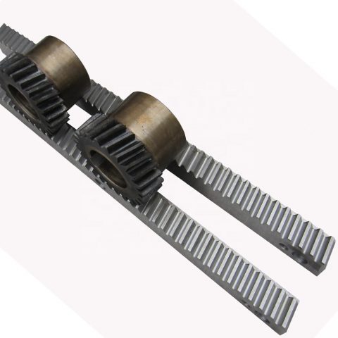 C45, SS304, SS316L, aluminum, copper, nylon and so on.
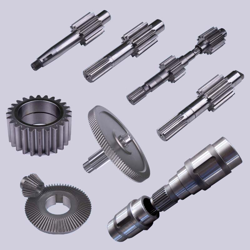 art metrology. With these machines, we generate complicated components from the most efficient and accurate way. Our manufacturing capabilities enable us to build your part from prototype to mass manufacturing for your most exact of jobs.
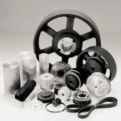 The bearing finish is constructed to ensure that the roller shaft and bearing is usually firmly connected.
 to supply manufacturer charges, with no the conventional distributor mark-up.
 veloped planetary gearbox delivers an enormous sum of torque and longevity to this Skid Steer Auger Push. Competing makers nevertheless use shafts inserted from the front, with problems of the shafts popping out when the retainer fails. EPG shafts are really inserted from the back again on a thrust plate that evenly distributes the excess weight. This presents you a distinct mechanical advantage and gives far more electricity at the bit. It also safeguards towards the shaft from popping out and makes your procedure much safer. EPG involves a life time guarantee towards any shaft pullout. Furthermore, the planetary gearbox is sealed with pre-installed lubrication, so there is no require for servicing. All you have to do is connect your auger bit and do what you do very best, work your compact products.
 put on on your tools and extend service lifestyle.
 x for your software. If your software requires a personalized drive solution, our engineers will team with you to design a parallel shaft gearbox that fulfills your exact software to reduce tension and wear on your tools and lengthen service lifestyle.
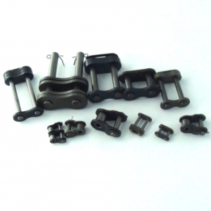 already proving effectiveness in mill duty centrifugal discharge elevators inside of the more difficult applications encountered within the cement market.
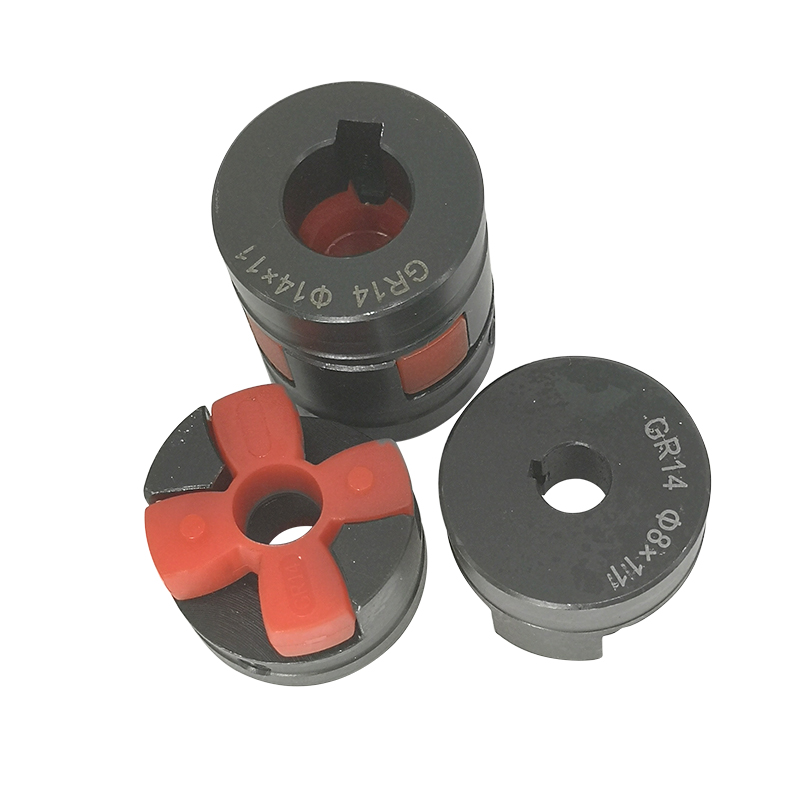 D19L25 5×10 D19L25 6×6 D19L25 6×6.35 D19L25 6×7 D19L25 6×8 D19L25 6×10 D19L25 6.35×6.35 D19L25 6.35X8 D19L25 6.35X10 D19L25 7×7 D19L25 7×8 D19L25 8×8 D19L25 8×10 D19L25 10×10
 oads/2019/10/Fluid-Couplings.jpg]#Recycling equipment
 d ON. The oil drains through calibrated orifices situated on the outer diameter of the fluid coupling. When it is turned OFF, it disengages the motor from the load.