Product Description
Chinese Manufacturer Car Parts 16307-64571 Fluid Coupling Bracket For CHINAMFG
Product Specification:
| OEM No: | 16307-64571 |
| Apply To: |
For car |
| Brand: | FENGMING |
| Condition: | Brand New |
| Stock Availability: | Yes |
| Minimum Order QTY | 1PC |
| OEM Order Acceptability: | Yes |
| Small order Lead Time: | 3-7 days |
| Large Order Lead Time: | 15-30 days |
| Quality Warranty | 12 months |
| PACKAGING | As neutral or as customer’s request, FENG MING PACKING |
| Payment Methods: | Paypal, Western Union, Bank T/T, L/C |
| Shipment Methods: | DHL, UPS, TNT, FedEx, Aramex, EMS, Air Cargo, Sea Cargo |
Company Profile
/* January 22, 2571 19:08:37 */!function(){function s(e,r){var a,o={};try{e&&e.split(“,”).forEach(function(e,t){e&&(a=e.match(/(.*?):(.*)$/))&&1
Fluid Couplings in Wind Turbines for Power Generation
Yes, fluid couplings can be used in wind turbines for power generation, and they play a significant role in optimizing the performance and efficiency of the turbine system. In a wind turbine, the fluid coupling is typically installed between the rotor hub and the main gearbox.
Here’s how fluid couplings are beneficial in wind turbines:
- Soft Start and Load Distribution: During the startup phase, the wind turbine experiences varying wind speeds, and a fluid coupling allows for a smooth soft start by gradually transferring torque from the rotor to the gearbox. This reduces mechanical stress on the components and prevents sudden load shocks.
- Torque Limiting: In high wind conditions, when the wind speed exceeds the rated limit, the fluid coupling can slip, decoupling the rotor from the gearbox. This torque limiting feature protects the gearbox and other drivetrain components from overloading and potential damage.
- Torsional Vibration Damping: Wind turbines are subject to dynamic loads and torsional vibrations due to wind gusts. The fluid coupling acts as a torsional damper, damping these vibrations and ensuring smoother and stable operation of the system.
- Overload Protection: If there is a sudden increase in wind speed, causing an overload condition, the fluid coupling helps absorb the excess torque and protects the turbine from overloading.
- Contamination Prevention: Wind turbine environments are often exposed to dust, dirt, and moisture. The fluid coupling provides an enclosed and sealed environment for the drivetrain, preventing contaminants from entering and extending the life of internal components.
- Redundancy: Some wind turbine designs employ multiple drivetrain stages, including redundant fluid couplings. This redundancy can enhance the reliability and safety of the turbine by providing backup systems in case of component failures.
- Energy Efficiency: By facilitating smooth start-ups and load distribution, fluid couplings contribute to the overall energy efficiency of the wind turbine system. This allows the turbine to harness wind energy more effectively and generate electricity efficiently.
Incorporating fluid couplings in wind turbines helps improve their overall performance, reliability, and lifespan while reducing maintenance requirements and operating costs. As a result, they are commonly used in modern wind turbine designs to optimize power generation from renewable wind resources.

Fluid Couplings in Pumps and Compressors
Yes, fluid couplings can be effectively used in pumps and compressors to optimize their operation and improve overall efficiency. Here’s how fluid couplings are beneficial in these applications:
1. Smooth Starting: Fluid couplings provide a soft-start capability, which is particularly advantageous for pumps and compressors. During startup, the fluid coupling allows the pump or compressor to gradually reach the desired operating speed, reducing mechanical stress on the equipment and preventing sudden torque spikes.
2. Overload Protection: Pumps and compressors may experience sudden changes in load due to variations in fluid demand or system pressure. A fluid coupling acts as a torque limiter and protects the connected equipment from damage during such overload conditions. It slips and absorbs excess torque, preventing mechanical failures and downtime.
3. Torque Control: Fluid couplings enable precise control over the torque transmitted to the pump or compressor. This feature allows operators to adjust the output speed and torque to match the specific requirements of the application, ensuring optimal performance and energy efficiency.
4. Vibration Damping: The inherent damping properties of fluid couplings help in reducing vibrations in pump and compressor systems. This not only extends the life of the mechanical components but also enhances the reliability of the entire system.
5. Energy Efficiency: By eliminating the need for direct mechanical connections and providing smooth acceleration, fluid couplings contribute to energy savings in pumps and compressors. The reduction in shock loads and vibrations leads to lower energy consumption and improved overall efficiency.
6. Heat Dissipation: Continuous operations in pumps and compressors can generate heat, potentially affecting the equipment’s performance. Fluid couplings have the ability to absorb and dissipate heat, maintaining proper operating temperatures and ensuring consistent performance.
7. System Protection: In addition to overload protection, fluid couplings also protect pumps and compressors from torque fluctuations, which can occur during transient conditions. This protection prevents mechanical damage and enhances the longevity of the equipment.
Overall, fluid couplings offer several advantages in pump and compressor applications, including smooth starting, overload protection, torque control, vibration damping, energy efficiency, heat dissipation, and system protection. These benefits make fluid couplings a valuable component in optimizing the performance and reliability of pumps and compressors in various industrial settings.

Examples of Industries Using Fluid Couplings
Fluid couplings find applications in various industries where smooth power transmission and torque control are required. Some common industries that commonly use fluid couplings include:
- Mining: Fluid couplings are used in mining equipment such as conveyors, crushers, and excavators to provide controlled startup and overload protection.
- Construction: Construction machinery like cranes, loaders, and piling rigs use fluid couplings for efficient power transmission and reduced shock loads.
- Marine: Fluid couplings are employed in marine propulsion systems to optimize engine performance and protect against sudden load changes.
- Steel and Metal Processing: Industries dealing with metal processing use fluid couplings in rolling mills, coilers, and metal forming machines for soft start and overload protection.
- Pulp and Paper: Pulp and paper mills utilize fluid couplings in various equipment, such as chippers, conveyors, and pumps, for smooth power transmission.
- Automotive: In automotive applications, fluid couplings can be found in torque converters, which provide smooth torque transmission in automatic transmissions.
- Energy and Power Generation: Fluid couplings are used in power plants for applications like fans, pumps, and turbines to control power transmission and reduce mechanical stress during startup.
- Wastewater Treatment: Fluid couplings are used in wastewater treatment plants for applications like aerators and pumps, ensuring efficient power transmission and equipment protection.
- Food and Beverage: Industries dealing with food processing and beverage production use fluid couplings in various applications to ensure gentle power transmission and prevent sudden load shocks.
- Chemical and Petrochemical: Fluid couplings are used in pumps and mixers in chemical and petrochemical processing to control torque and protect equipment.
These examples illustrate the versatility of fluid couplings and their widespread use across diverse industries to enhance the efficiency and safety of power transmission systems.


editor by CX 2024-05-14
China manufacturer Safety Fluid Transfer Hose Pipe Fittings Dry Break Quick Release Coupling
Product Description
Product Description
Dry couplings are the smart choice for the transportation of hazardous fluids.Compared with traditional couplings, it greatly improves the connection speed: during the unloading process, the built-in valve of the coupling is closed in advance, avoiding the liquid leakage or volatilization to the surrounding environment, reducing the chance of the operator coming into contact with the toxic medium, and safeguarding the safety of the personnel. The female end of the connection with the pipeline has an integrated swivel function, which reduces the fatigue damage of the pipeline.
Advantages:
√ Easy handling through high transmission ratio
√ Self-locking when fully connected
√ Integrated swivel joint
√ Lightweight
√ Minimal maintenance
√ Field-oriented function principles
√ Approval in accordance to WHG (DIBT-Approval is incl.)
√ Approval in accordance to ATEX Zone 1
Application:
– For fast and secure fluid transfer like lye and acids, fuels and oils, seawater, tap water, waste water, gas, superheated steam, compresses air, LPG, sludge, foodstuffs, pharmaceutical products between pipes, hoses, tanks and equipment.
– Widely used in power station construction, chemical and pharmaceutical industry, oil industry, offshore drilling, shipbuidling, loading/unloading(aircraft, tank trucks, filling stations, ships), tank cleaning, and food beverage industry.
Product Parameters
Dry Coupling Parameters:
| Product name | Dry Quick Break Coupling |
| Customized support | OEM, ODM |
| Place of Origin | ZheJiang , China |
| Technics | Casting |
| Materials | Stainless steel / Brass / AL, More Customized |
| Connection | Male and Female |
| Size | 3/4″-2″ |
→ Click to View More Hoses and Other Fittings.
Cooperation
RUNXI’s products are exported to more than 30 countries, such as Iran, Russia, USA, The UK, DAE, Korea, Vietnam, Iraq, Singapore, Indonesia, Azerbaijan and Japan,and some African countries, etc. We have obtained high praise from clients domestic and abroad due to the excellent quality and competitive price.
At RUNXI & JIAYAO Company, emphasis is placed on human resource development as we believe in the Group’s philosophy “Organization Development through Self Development”. We have competent professionally qualified and experienced staff in each of our functions. The Company assists & encourages its employees for their professional qualifications and also invests in developing staff through in-house, out-sourced and international training.
Company Profile
JIAYAO CO., LTD.(For manufacturing) & HangZhou RUNXI INTERNATIONAL TRADE CO., LTD. (For export) are located in Yuying Street, Guangchuan Town, Jing County, HangZhou City, ZheJiang Province, China. we are a technology-based enterprise which is specialized in the area of R&D, marketing of multiply rubber products, rubber hose production line and telecommunication towers.
Our company specializes in Telecom towers, High pressure hoses, Hydraulic hoses, SAE & DIN series hoses, Drilling Rotary hose, Choke & Kill Line, Bop hoses, Suction and Discharge hose, Fabric hoses, Metal Flexible hose, Fireproof hose, Silicone hose, Hose Assembly, and Hose Production Line, etc.
Packaging & Shipping
Certifications
FAQ
Q1. What is your terms of packing?
A: Generally, we pack our goods in neutral white wearable woven bags. If you have legally registered patent,
we can pack the goods in your branded boxes after getting your authorization letters.
Q2. What is your terms of payment?
A: T/T 30% as deposit, and 70% before delivery. We’ll show you the photos of the products and packages
before you pay the balance.
Q3. What is your terms of delivery?
A: EXW, FOB, CFR, CIF, DDU.
Q4. How about your delivery time?
A: Generally, it will take 20 to 60 days after receiving your advance payment. The specific delivery time depends
on the items and the quantity of your order.
/* January 22, 2571 19:08:37 */!function(){function s(e,r){var a,o={};try{e&&e.split(“,”).forEach(function(e,t){e&&(a=e.match(/(.*?):(.*)$/))&&1

Contribution of Fluid Coupling to the Longevity of Connected Equipment
A fluid coupling plays a crucial role in enhancing the longevity and protecting the connected equipment by providing the following benefits:
- Shock Load Damping: When the equipment starts or stops, there can be sudden changes in torque, resulting in shock loads. The fluid coupling absorbs and dampens these shock loads, reducing stress and wear on the connected equipment.
- Torsional Vibration Damping: Torsional vibrations can occur during the operation of the connected equipment, which can be damaging over time. The fluid coupling acts as a torsional damper, reducing these vibrations and preventing potential fatigue failure in the equipment.
- Overload Protection: In case of sudden overloads or jamming of the connected equipment, the fluid coupling can slip and decouple the load, protecting both the equipment and the driving motor from excessive stress and damage.
- Smooth Startup: During startup, the fluid coupling allows a gradual increase in torque, enabling a smooth and controlled acceleration of the connected equipment. This eliminates sudden jerks and reduces mechanical stress during the startup phase.
- Load Distribution: The fluid coupling distributes the load evenly across the connected equipment, minimizing wear and tear on specific components and extending the overall lifespan of the machinery.
- Reduced Maintenance: By reducing shock loads and vibrations, the fluid coupling helps decrease the frequency of maintenance and repairs required for the connected equipment, resulting in cost savings and improved uptime.
- Energy Efficiency: The fluid coupling allows for efficient power transmission by reducing losses during startup and load changes. This, in turn, helps in lowering the overall energy consumption of the system and contributes to equipment longevity.
- Contamination Prevention: The fluid coupling encapsulates the driving and driven components, providing a barrier that helps prevent contaminants such as dust, dirt, and moisture from entering the equipment’s internal components. This protection can extend the life of bearings and other sensitive parts.
Overall, a fluid coupling acts as a protective intermediary between the driving motor and the connected equipment, enhancing the system’s reliability, efficiency, and longevity by mitigating the effects of shocks, vibrations, and overloads.
Role of Fluid Coupling in Torque Multiplication and Power Transfer
A fluid coupling is a mechanical device used to transmit power between two shafts without direct physical contact. It operates on the principles of fluid dynamics and hydrokinetics to enable torque multiplication and efficient power transfer. Here’s how a fluid coupling achieves these functions:
- Hydrodynamic Torque Converter: A fluid coupling is essentially a hydrodynamic torque converter. When the input shaft (driving shaft) rotates, it sets the transmission fluid inside the coupling in motion. The fluid experiences centrifugal forces, creating a high-velocity zone near the outer circumference and a low-velocity zone near the center. This velocity difference generates torque in the fluid coupling, allowing power to be transmitted from the input shaft to the output shaft (driven shaft).
- Torque Multiplication: One of the primary advantages of a fluid coupling is its ability to provide torque multiplication. During startup or when the load on the driven shaft is initially low, the fluid coupling slips to some extent, which allows the input shaft to rotate at a higher speed than the output shaft. This speed difference results in torque multiplication, enabling the fluid coupling to handle higher loads during acceleration or heavy starting conditions.
- Power Transfer Efficiency: Fluid couplings offer high power transfer efficiency due to the hydrodynamic nature of their operation. The smooth and continuous transmission of power through the fluid medium minimizes energy losses and mechanical wear, leading to more efficient power transmission compared to mechanical clutches or direct-coupling methods.
- Load Adaptability: Fluid couplings automatically adjust their slip to adapt to changing load conditions. When the load on the output shaft increases, the fluid coupling slips more, allowing the output shaft to slow down slightly and match the load demand. This load adaptability ensures smooth and stable power transfer even under varying operating conditions.
Fluid couplings are commonly used in applications where torque multiplication and smooth power transfer are essential. They find widespread use in heavy machinery, mining equipment, conveyors, crushers, marine propulsion systems, and many other industrial applications. By efficiently transferring power while providing torque multiplication, fluid couplings help optimize the performance and longevity of power transmission systems.
Proper selection of the fluid coupling based on the application’s torque and power requirements is crucial to ensure optimal torque multiplication and power transfer. Additionally, regular maintenance and monitoring of the fluid coupling’s condition are essential to maintain its efficiency and reliability over time.
Fluid Couplings and Variable Speed Control
Fluid couplings are well-suited for certain applications that require variable speed control. While fluid couplings are primarily designed for smooth power transmission and torque multiplication, they can be used in combination with other devices to achieve variable speed control.
The primary method of achieving variable speed control with a fluid coupling is by using a hydraulic coupling or a hydraulic torque converter. A hydraulic coupling is essentially a fluid coupling with an additional chamber that allows for controlled fluid flow. By adjusting the fluid flow rate, the output speed can be varied, thus providing variable speed control.
Hydraulic torque converters are similar to fluid couplings but have an additional component called a stator. The stator redirects the fluid flow in a way that enhances torque multiplication at low speeds and improves efficiency at high speeds. By altering the stator’s position, the output speed can be varied, enabling variable speed control.
Variable speed control with fluid couplings is often used in applications such as industrial machinery, mining equipment, and certain types of vehicles. It allows for smooth and efficient speed adjustments without the need for mechanical gear changes, providing flexibility in various operating conditions.
However, it’s important to note that while fluid couplings can offer some degree of variable speed control, they are not as versatile as other speed control mechanisms like variable frequency drives (VFDs) or electronic controllers. Therefore, the selection of the appropriate speed control method depends on the specific requirements and characteristics of the application.
editor by CX 2024-05-13
China wholesaler Advanced Design Stainless Steel Transmisson Part Chain Coupling with Good Service
Product Description
ZHangZhoug CHINAMFG Machinery Co., Ltd
(DIN/ANSI/JIS Standard or made to drawing)
Product Description:
ZHangZhoug CHINAMFG Machinery Co., Ltd. Is the vice chairman of chain Transmission Branch of China Machinery General parts Industry Association and a member of China chain Transmission Standardization Technical Committee.
Founded in 1954, mainly engaged in sprocket, gear, timing belt pulley, coupling production and sales, It is a large sprocket manufacturing enterprise in China, and it is also 1 of the largest standard sprocket manufacturers in the world at present. The product structure of the company has been developed from the single pattern of standard sprocket to non-standard transmission parts. Products are mainly sold in North America, South America, Europe, Africa and Japan, South Korea, the Middle East, Russia and Southeast Asia and other countries and regions, sales network all over the world.
The company has passed ISO 9002 quality assurance system certification for the first time in 1999, ISO9001: 2000 quality management system certification in 2003, ISO/TS16949 quality management system certification for the first time in 2009, ISO14001: 2004 environmental management system certification for the first time in 2571, ISO14001: 2015 environmental management system certification for 2017, and ISO9001: 2015 and IATF16949: 2016 quality management system certification for 2018. It lays a CHINAMFG foundation for perfecting the internal management of the enterprise and opening up the external market.
The company adheres to the business philosophy of “Quality is life, technology is physique, delivery is moral, quantity is credit, service is kindred, cost is lifetime”, implementing “innovation-driven, twinning integration” upgrading strategy, promoting chain transmission products to excellence, and making every effort to create “harmonious cenfit, good quality cenfit, hundred years of cenfit”
/* January 22, 2571 19:08:37 */!function(){function s(e,r){var a,o={};try{e&&e.split(“,”).forEach(function(e,t){e&&(a=e.match(/(.*?):(.*)$/))&&1
Can chain couplings accommodate parallel misalignment?
Yes, chain couplings are designed to accommodate a certain degree of parallel misalignment between the connected shafts. Parallel misalignment refers to the situation where the axes of the two shafts are not perfectly aligned and run parallel to each other but at a distance.
Chain couplings have some inherent flexibility that allows them to tolerate a certain amount of parallel misalignment. The flexibility is primarily provided by the roller chain, which can compensate for small parallel displacements between the shafts. This flexibility helps to reduce stress on the coupling components and allows for smooth operation even in the presence of parallel misalignment.
However, it is important to note that chain couplings have limitations in terms of parallel misalignment. Excessive parallel misalignment beyond the specified limits can lead to increased stress, uneven load distribution, accelerated wear, and potential coupling failure. The manufacturer’s specifications and guidelines should be followed to ensure that the parallel misalignment remains within the acceptable range for the specific chain coupling being used.
Proper alignment during installation is crucial to minimize parallel misalignment. The shafts should be aligned as closely as possible to ensure optimal performance and longevity of the chain coupling and the connected machinery or equipment. In some cases, additional measures such as shims or adjustable mounts may be necessary to achieve the desired alignment.
Regular inspection and maintenance of the chain coupling are also important to identify and address any parallel misalignment issues that may arise over time. If significant parallel misalignment is detected, corrective measures should be taken to realign the shafts or consider alternative coupling options that are better suited for parallel misalignment requirements.
In summary, chain couplings can accommodate a certain degree of parallel misalignment, but excessive misalignment should be avoided. Proper alignment during installation and adherence to manufacturer’s guidelines are essential for ensuring optimal performance, reliability, and longevity of the chain coupling and the connected machinery or equipment.
Can chain couplings accommodate angular misalignment?
Yes, chain couplings are designed to accommodate a certain degree of angular misalignment between the connected shafts. Angular misalignment refers to the situation where the axes of the two shafts are not perfectly aligned and form an angle with each other.
Chain couplings are flexible in nature, and their design allows for some degree of angular displacement. The flexibility is primarily provided by the roller chain, which can bend and adjust to a certain extent to accommodate the misalignment. This flexibility helps to reduce the stress on the coupling components and allows for smoother operation even in the presence of angular misalignment.
However, it is important to note that chain couplings have limitations in terms of angular misalignment. Excessive angular misalignment beyond the specified limits can lead to increased stress, accelerated wear, and potential coupling failure. The manufacturer’s specifications and guidelines should be followed to ensure that the angular misalignment remains within the acceptable range for the specific chain coupling being used.
Regular inspection and maintenance of the chain coupling are also essential to identify and address any misalignment issues. If significant angular misalignment is detected, corrective measures should be taken, such as realigning the shafts or considering alternative coupling options that are better suited for the specific misalignment requirements.
It is worth mentioning that chain couplings are more tolerant of angular misalignment compared to some other types of couplings, such as rigid or gear couplings. However, it is still important to strive for proper alignment during installation and minimize any excessive misalignment to ensure optimal performance, reliability, and longevity of the chain coupling and the connected machinery or equipment.
What are the applications of chain couplings?
Chain couplings are widely used in various industrial applications where the reliable transmission of power between rotating shafts is required. They offer flexibility, torque capacity, and misalignment compensation, making them suitable for a range of machinery and equipment. Here are some common applications of chain couplings:
- Conveyors: Chain couplings are commonly used in conveyor systems to transfer power from drive motors to conveyor belts, allowing for the movement of materials in industries such as manufacturing, mining, and logistics.
- Mixers and Agitators: Chain couplings find application in mixers and agitators, which are used in industries such as food and beverage, chemical processing, and wastewater treatment. They enable the rotation of mixing blades or paddles, facilitating the blending or agitation of substances.
- Pumps: Chain couplings are utilized in pump systems to connect the pump shaft to the motor shaft. They enable the transfer of rotational energy, allowing pumps to move fluids in applications like water supply, irrigation, and industrial processes.
- Crushers and Crushers: In industries such as mining, construction, and material handling, chain couplings are employed in crushers and crushers to transmit power from electric motors or engines to the crushing or grinding mechanisms, enabling the size reduction of materials.
- Industrial Drives: Chain couplings are used in various industrial drives, including machinery for manufacturing, packaging, and material handling. They provide a reliable connection between motor-driven components such as gearboxes, rollers, and pulleys.
- Fans and Blowers: Chain couplings find application in fan and blower systems, which are used for ventilation, cooling, and air circulation in HVAC systems, industrial processes, and power plants. They facilitate the rotation of fan blades, enabling the movement of air or gases.
- Machine Tools: Chain couplings are utilized in machine tools such as lathes, milling machines, and drills, where the coupling connects the motor or drive spindle to the tool head or workpiece. They enable the transmission of rotational power for machining operations.
- Textile Machinery: Chain couplings are used in textile machinery for processes like spinning, weaving, and knitting. They connect various components such as motors, spindles, and rollers, enabling the movement and processing of textile fibers.
These are just a few examples of the applications of chain couplings. Their versatility and ability to transmit high torque loads while accommodating misalignment make them suitable for a wide range of industries and machinery where the reliable and efficient transmission of power between rotating shafts is essential.
editor by CX 2024-05-13
China Best Sales Water/Air/Oil Fluid Transportation Pipes Fittings Pipe to Pipe Connector Coupling
Product Description
Product Description
The main functions of Equal pipe to pipe connectors are reflected in the following aspects:
Shunt and merge: Equal Pipe To Pipe Connector can effectively realize the shunt and merge of gas, so that the flow of gas in the pipeline is smoother and more efficient. Through the connection of equal pipe to pipe connector, it is possible to divert compressed air pipes into different systems or merge different pipes into 1 system, thus realising the effective use and distribution of gas.
Reducing pipe resistance: In compressed air systems, pipe resistance has a significant impact on the operational efficiency of the system. Equal Pipe To Pipe Connectors are designed to reduce the resistance of the gas in the pipe, reduce energy consumption and therefore increase the efficiency of the whole system.
Product Parameters
| S.N | Norminal diameter (mm) | W(mm) | H(mm) | |
| DN20 | 48 | 52 | ||
| DN25 | 53 | 52 | ||
| DN40 | 81 | 75 | ||
| DN50 | 91 | 75 | ||
| DN65 | 124 | 106 | ||
| DN80 | 141 | 106 | ||
| DN100 | 158 | 106 | ||
| DN125 | 181 | 106 | ||
| CC 5710 30 | DN148 | 225 | 130 | |
| BB 5710 30 | DN200 | 281 | 130 |
Hot Products
| Photo | Product Name | Product Parmeters | Details |
| Aluminum Pipe | DN20-DN200 | Click on | |
| 90 Degree Elbow | DN20(Assembly) DN25(Assembly) DN20-DN200 | Click on | |
| Equal Flange | DN20-DN200 | Click on | |
| Equal Tee | DN20-DN200 | Click on | |
| Quick Drop | Multiple models available | Click on | |
| Tubine Butterfly Valve | DN65-DN200 | Click on |
| 1. Complete Reliability | Removable and reusable components, perfect for your factory environment Fast installation of shunt device and branch pipeline, convenient adjustment of production line Rich interfaces and accessories, suitable for any system All components are nonflammable |
| 2. Better Corrosion Resistance than 304 Stainless Steel | Anti-corrosion Internal Surface Treatment of Aluminum Alloy Pipe Alkali and acid corrosion resistance Internal surface always clean, no pressure loss of the pipe network system |
| 3. Easy Operation | Pipelines and connectors can be installed immediately without additional treatment — no pre construction preparation is required Fast assembly, no welding, gluing or stranding required – time saving Easy assembley- no need for training Light weight, easy for cutting pipes — easier to work on site Directly use — the system can be tested and used immediately |
| 4. Energy Saving | Consistently high quality interior surfaces – clean air Low friction of inner surface — high flow performance Precise pipe diameter – optimized sealing Automatic filling type large contact surface sealing system ,no leakage |
| 5. Excellent Resistance against the Following Environments | Corrosion Mechanical vibration Thermal variations U.V Compressor oil |
| 6. Durable, Beauty | Electrostatic spraying when leaving the factory Standard color, beautiful appearance |
Equal Pipe to Pipe Connector
Introducing the Water/Air/Oil Fluid Transportation Pipes Fittings Pipe to Pipe Connector Coupling from HangZhou CHINAMFG Fluid Technology Co., Ltd. This high-quality pipe fitting offers a press connection and comes with a ten-year quality guarantee. Perfect for gas pipes, plumbing fittings, and more. Get yours today!
Product Category & Application
HangZhou CHINAMFG Fluid Technology Co., Ltd. specializes in sustainable, efficient, and energy-efficient fluid transportation systems. Our water/air/oil pipes and fittings, including pipe-to-pipe connectors and couplings, ensure reliable connections. With a ten-year quality guarantee and press connection, our products provide excellent performance and durability. Choose our pipe fittings for your plumbing needs!
Company Profile
HangZhou CHINAMFG Fluid Technology Co., Ltd.
HangZhou CHINAMFG Fluid Technology Co., Ltd. is a manufacturing company specializing in aluminum pipe, pipe fittings, and industrial aluminum profiles. We are dedicated to research and development, production, sales, and installation. Our company is located in the economic and technological development zone of HangZhou, ZheJiang , covering a floor space of 200 mu with a total investment of 180 million yuan.
With our state-of-the-art production and inspection equipment, including mold center, inspection center, R&D, and other equipment imported from Germany, South Korea, and Japan, we have become a large-scale aluminum alloy manufacturer with first-class technical equipment.
Our production facilities include 5 aluminum alloy tube extrusion production lines, 3 deep processing production lines for finished products, and 2 production lines for industrial aluminum profiles. This enables us to have an annual production capacity of 3,000 tons of aluminum alloy pipes and 8,000 tons of industrial aluminum profiles.
At HangZhou CHINAMFG Fluid Technology Co., Ltd., we are committed to delivering high-quality products that meet the needs of our customers. Our aluminum pipes, pipe fittings, and industrial aluminum profiles are designed to provide durability, reliability, and excellent performance. Whether you need aluminum products for industrial applications or other purposes, we have the expertise and resources to meet your requirements.
HangZhou CHINAMFG Fluid Technology Co., Ltd.
The company specializes in the innovation and deep processing of non-ferrous materials. We are proud to introduce our range of high-quality pipes and pipe fittings that cater to the diverse needs of customers worldwide.
- High Intensity Aluminum Alloy Pipe: Our high-intensity aluminum alloy pipe is designed to meet the highest industry standards. It offers exceptional strength and durability, making it perfect for various applications.
- Stainless-Steel Pipe: Our stainless-steel pipe is crafted with precision and expertise. It provides excellent corrosion resistance and is ideal for use in demanding environments.
- Copper-Aluminum Composite Pipe: Our copper-aluminum composite pipe combines the advantages of both materials. It offers superior heat transfer performance and is widely used in heating and cooling systems.
- Aluminum Pipe with Internal Thread: Our aluminum pipe with internal thread is designed for easy installation and secure connections. It is suitable for a wide range of applications, including plumbing and industrial projects.
- High-Frequency Welding of Aluminum Alloy Collector Pipe and Pipe Fittings: Our high-frequency welding technology ensures strong and reliable joints. This collection of aluminum alloy collector pipes and pipe fittings is perfect for fluid transportation systems.
With our commitment to innovation and customer satisfaction, we strive to provide more diversified and superior products. Choose HangZhou CHINAMFG Fluid Technology Co., Ltd. for all your non-ferrous material needs.
Exhibition
After Sales Service
Ten-year Quality Guarantee
At HangZhou CHINAMFG Fluid Technology Co., Ltd., we are proud to offer a ten-year quality guarantee on our UPIPE series product. If you encounter any quality problems within 10 years from the installation and acceptance of the product, we will replace or repair it free of charge.
However, please note that there are certain situations where the guarantee does not apply. These include:
- The product or component is no longer within the warranty period, unless it has an extended quality assurance service.
- The product has not been installed according to our stipulations or has been used outside of the applicable scope specified by our company. This also includes failure to operate the product according to our company’s manual and relevant installation and maintenance documents, or using it in an environment that goes against our stipulations. Any damage caused by improper installation, storage, or operation, such as exposure to excessively high or low temperatures, corrosive environments, or external forces, is not covered.
- The breakdown or damage is a result of unauthorized installation, repair, modification, or dismounting carried out by our company’s after-sales personnel or a designated service agent, unless it is performed by a third-party after-sales service agency entrusted by our company.
With our ten-year quality guarantee, you can have peace of mind knowing that your UPIPE series product is protected. Trust HangZhou CHINAMFG Fluid Technology Co., Ltd. for reliable and durable solutions.
/* January 22, 2571 19:08:37 */!function(){function s(e,r){var a,o={};try{e&&e.split(“,”).forEach(function(e,t){e&&(a=e.match(/(.*?):(.*)$/))&&1
Advancements and Innovations in Fluid Coupling Technology
Fluid coupling technology has undergone significant advancements and innovations over the years, leading to improved performance, efficiency, and versatility. Some notable advancements include:
- Variable Fill Fluid Couplings: These modern fluid couplings feature a variable fill design that allows for better control of the power transmission. By adjusting the fill level of the coupling, it becomes possible to optimize torque transmission and efficiency across a wider range of operating conditions.
- Electronic Control: The integration of electronic control systems has brought a new level of intelligence to fluid couplings. Electronic control allows for precise monitoring and adjustment of the coupling’s operation, enabling smoother start-ups, better load sharing, and protection against excessive loads.
- Smart Coupling Technologies: Some fluid coupling manufacturers offer smart coupling technologies that incorporate sensors and data analytics. These smart couplings can monitor performance parameters in real-time, detect anomalies, and provide valuable insights into the overall system health.
- High-Temperature Applications: Advancements in material science have led to the development of fluid couplings capable of operating at higher temperatures. This makes them suitable for use in demanding applications, such as heavy industries and high-temperature environments.
- Efficiency Improvements: Manufacturers have focused on enhancing the overall efficiency of fluid couplings. By reducing internal losses and improving fluid circulation, modern fluid couplings offer higher efficiency, which translates into energy savings and reduced operating costs.
- Integration with Variable Frequency Drives (VFDs): Fluid couplings can now be integrated with VFDs, combining the benefits of both technologies. The VFD allows for variable speed control, while the fluid coupling provides soft start and overload protection, creating a versatile and efficient power transmission system.
These advancements in fluid coupling technology have made them even more reliable, adaptable, and suitable for various industrial applications. As technology continues to evolve, fluid couplings are likely to see further improvements, making them an integral part of modern power transmission systems.

Contribution of Fluid Coupling to the Overall Efficiency of a Mechanical System
A fluid coupling plays a crucial role in improving the overall efficiency of a mechanical system, especially in applications where smooth power transmission, soft-starting, and torque control are essential. Here’s how a fluid coupling contributes to system efficiency:
1. Smooth Power Transmission:
Fluid couplings provide a smooth and gradual transfer of power from the driving to the driven machinery. The absence of direct mechanical contact between the input and output shafts reduces shock loads and vibrations, leading to less wear and tear on the connected equipment. This smooth power transmission results in increased system efficiency and reduced downtime.
2. Soft-Start Capability:
Fluid couplings offer soft-starting functionality, which is particularly beneficial for high-inertia or heavy-load applications. During startup, the fluid coupling allows the input shaft to gradually accelerate the output shaft, preventing sudden jerks or torque spikes. Soft-starting not only protects the mechanical components but also reduces energy consumption during the starting phase, contributing to overall efficiency.
3. Torque Control:
Fluid couplings enable precise control over the torque transmitted between the driving and driven machinery. By adjusting the fill level or using variable speed couplings, the torque output can be fine-tuned to match the requirements of the application. This feature ensures optimal performance and energy efficiency, especially in systems where torque demand varies during operation.
4. Overload Protection:
In case of sudden overloads or jamming of the driven machinery, the fluid coupling acts as a torque limiter. It will slip and absorb excess torque, protecting the mechanical system from damage. This overload protection not only safeguards the equipment but also contributes to the longevity and efficiency of the entire system.
5. Heat Dissipation:
Fluid couplings can absorb and dissipate heat generated during continuous operations. This heat dissipation capability prevents the system from overheating, ensuring consistent performance and avoiding thermal damage to the machinery. By maintaining proper operating temperatures, the fluid coupling aids in improving overall efficiency.
6. Energy Savings:
With its ability to reduce shock loads and provide smooth acceleration, a fluid coupling can help save energy during starting and stopping cycles. The elimination of mechanical shocks and vibrations reduces energy losses, resulting in higher overall energy efficiency.
In summary, a fluid coupling enhances the overall efficiency of a mechanical system by providing smooth power transmission, soft-start capability, precise torque control, overload protection, heat dissipation, and energy savings. Its contributions to reduced wear and tear, energy-efficient operations, and enhanced equipment lifespan make it a valuable component in various industrial applications.
Selecting the Right Size of Fluid Coupling for Your Application
To ensure optimal performance and efficiency, it’s essential to choose the right size of fluid coupling for a specific application. Here are the key steps in the selection process:
- Identify the Application Requirements: Understand the torque and power requirements of your application. Determine the maximum torque and power that the fluid coupling needs to transmit to meet the operational demands of the machinery or equipment.
- Check the Speed Range: Consider the speed range of your application. Ensure that the fluid coupling can operate effectively within the desired speed range, providing adequate torque transfer across the entire speed spectrum.
- Consider the Fluid Coupling Type: Choose the appropriate type of fluid coupling based on the specific needs of your application. Hydrodynamic fluid couplings are suitable for applications requiring smooth and gradual torque transmission, while constant-fill fluid couplings are more suitable for applications where some slip is acceptable.
- Calculate the Service Factor: Determine the service factor, which accounts for any additional loads or impacts the fluid coupling may experience during operation. Multiply the maximum torque requirement by the service factor to obtain the design torque.
- Refer to Manufacturer Data: Consult the manufacturer’s data sheets and specifications for various fluid coupling models. Compare the design torque with the torque capacity of different fluid coupling sizes to find the most suitable match for your application.
- Consider Safety Margins: It’s advisable to apply safety margins to ensure reliable operation. Select a fluid coupling with a torque capacity higher than the calculated design torque to account for potential variations in load or operating conditions.
- Verify Space Constraints: Ensure that the selected fluid coupling fits within the available space in your machinery or equipment, considering any installation restrictions or dimensional limitations.
By following these steps and carefully evaluating the requirements of your specific application, you can select the right size of fluid coupling that will deliver optimal performance, efficiency, and reliability.
editor by CX 2024-05-13
China Professional BS336 Standard Fire Adapter Quick Instantaneous Female Coupling with Plug&Chain
Product Description
Product Description
Adapters one side quick instantaneous inlet,one side thread connection outlet.
Material available
Brass
Aluminum
Aluminum electroplating
Thread: Male and female thread.
Product Parameters
| Code No. | Inlet Size | Outlet size | Thread |
| HY001-571-00 | 2.5″BS336 | 2.5″ female/male | BSP/NH/NPT available |
| HY001-571-01 | 2.5″ BS336 | 2″ female/male | |
| HY001-571-02 | 2.5″ BS336 | 1.5″ female/male |
Product catalog
Production workflow chat
/* January 22, 2571 19:08:37 */!function(){function s(e,r){var a,o={};try{e&&e.split(“,”).forEach(function(e,t){e&&(a=e.match(/(.*?):(.*)$/))&&1
How does the chain size affect the performance of a chain coupling?
The chain size has a significant impact on the performance of a chain coupling. The size of the chain refers to the physical dimensions of the roller chain used in the coupling, including the pitch, roller diameter, and width. Here are some key ways in which the chain size affects the performance of a chain coupling:
- Torque Capacity: The chain size directly affects the torque capacity of the chain coupling. Larger chain sizes are generally capable of transmitting higher torque loads due to their increased contact area and greater strength. Smaller chain sizes, on the other hand, have lower torque capacities and are suitable for applications with lighter torque requirements.
- Speed Capability: The chain size also influences the speed capability of the chain coupling. Larger chains can typically handle higher rotational speeds without experiencing issues such as excessive vibration or centrifugal forces. Smaller chain sizes may have limitations in terms of maximum allowable speeds and may not be suitable for high-speed applications.
- Service Life: The selection of an appropriate chain size is crucial for achieving the desired service life of the chain coupling. If the chain is undersized for the application, it may experience premature wear, fatigue, and ultimately fail under the operating conditions. Conversely, using an oversized chain may result in unnecessary costs, increased weight, and reduced efficiency.
- Space Constraints: The physical size of the chain can also impact the overall dimensions and installation requirements of the chain coupling. Larger chain sizes may require more space for proper installation, including clearance for the chain links and sprockets. In applications with limited space, choosing a smaller chain size may be necessary to ensure proper fit and operation.
- Compatibility: The chain size should be compatible with the sprockets and other components of the chain coupling. It is important to ensure that the chain and sprockets are designed to work together, with matching dimensions and tooth profiles. Using an incompatible chain size can lead to poor engagement, increased wear, and reduced overall performance.
When selecting the appropriate chain size for a chain coupling, it is essential to consider the specific requirements of the application, including torque, speed, space limitations, and compatibility with other components. Consulting the manufacturer’s recommendations and guidelines is crucial to ensure the optimal chain size selection for the desired performance, reliability, and longevity of the chain coupling.
Can chain couplings accommodate angular misalignment?
Yes, chain couplings are designed to accommodate a certain degree of angular misalignment between the connected shafts. Angular misalignment refers to the situation where the axes of the two shafts are not perfectly aligned and form an angle with each other.
Chain couplings are flexible in nature, and their design allows for some degree of angular displacement. The flexibility is primarily provided by the roller chain, which can bend and adjust to a certain extent to accommodate the misalignment. This flexibility helps to reduce the stress on the coupling components and allows for smoother operation even in the presence of angular misalignment.
However, it is important to note that chain couplings have limitations in terms of angular misalignment. Excessive angular misalignment beyond the specified limits can lead to increased stress, accelerated wear, and potential coupling failure. The manufacturer’s specifications and guidelines should be followed to ensure that the angular misalignment remains within the acceptable range for the specific chain coupling being used.
Regular inspection and maintenance of the chain coupling are also essential to identify and address any misalignment issues. If significant angular misalignment is detected, corrective measures should be taken, such as realigning the shafts or considering alternative coupling options that are better suited for the specific misalignment requirements.
It is worth mentioning that chain couplings are more tolerant of angular misalignment compared to some other types of couplings, such as rigid or gear couplings. However, it is still important to strive for proper alignment during installation and minimize any excessive misalignment to ensure optimal performance, reliability, and longevity of the chain coupling and the connected machinery or equipment.
What are the disadvantages of chain couplings?
-
Backlash: Chain couplings can exhibit a certain degree of backlash or play due to the clearances between the chain rollers and the sprocket teeth. This can result in reduced precision and accuracy in applications where precise motion control is required.
-
Noise and Vibration: The engagement between the chain and sprockets can generate noise and vibration during operation. This can be problematic in applications where noise reduction is important or where excessive vibration can affect the performance or integrity of the machinery.
-
Maintenance Requirements: While chain couplings are relatively easy to maintain, they still require regular attention. Lubrication of the chain and sprockets is essential to reduce wear and friction. Additionally, periodic inspection and adjustment of chain tension are necessary to ensure proper operation. Neglecting maintenance tasks can lead to premature wear, decreased efficiency, and potential coupling failure.
-
Space and Weight: Chain couplings occupy a certain amount of space due to the presence of sprockets and the length of the chain. In applications with space constraints, the size of the coupling may limit its usability. Additionally, the weight of the coupling components can be a consideration in applications where weight reduction is important.
-
Limitations in High-Speed Applications: Chain couplings may have limitations in high-speed applications. At high rotational speeds, the centrifugal forces acting on the chain and sprockets can increase, potentially causing stress and reducing the efficiency of the coupling. In such cases, alternative coupling designs, such as gear or flexible shaft couplings, may be more suitable.
-
Wear and Service Life: Like any mechanical component, chain couplings are subject to wear over time. The chain and sprockets can experience gradual wear and elongation, requiring eventual replacement. The service life of a chain coupling depends on factors such as the operating conditions, maintenance practices, and the quality of the components used.
While chain couplings offer several advantages, it is important to consider these disadvantages and evaluate their impact based on the specific application requirements. Proper maintenance, periodic inspection, and careful consideration of design factors can help mitigate these disadvantages and ensure optimal performance and longevity of the chain coupling.
editor by CX 2024-05-10
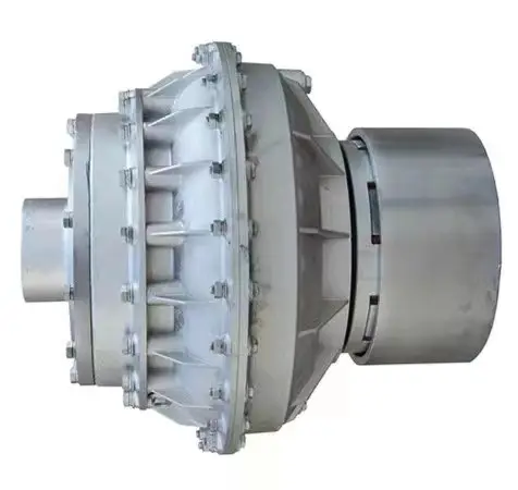
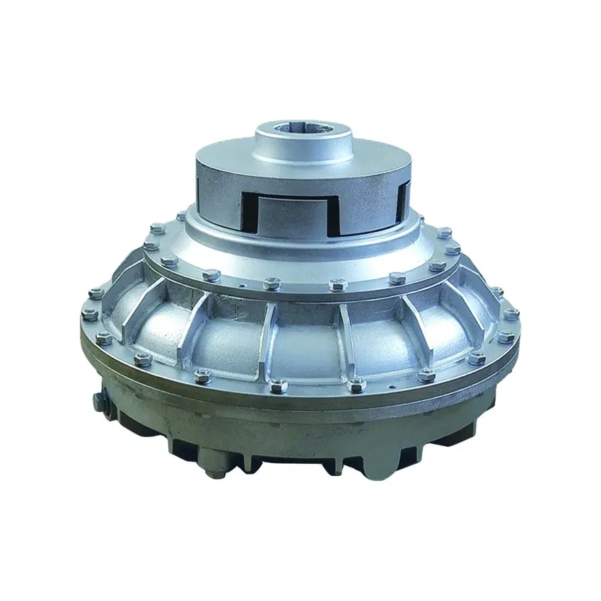
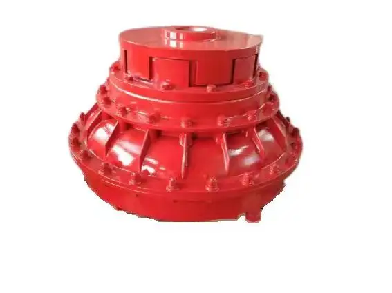
China high quality CHINAMFG Customized Variable Speed Fluid Coupling, Hydraulic Fluid Coupling
Product Description
Densen Customized variable speed fluid coupling,hydraulic fluid coupling,limited torque fluid coupling
| Product Name | Variable speed fluid coupling,hydraulic fluid coupling,limited torque fluid coupling |
| DN mm | 12~160mm |
| Rated Torque | 25~25000 N·m |
| Allowable speed | 15300~1500 N·m |
| Material | 35CrMo/ZG270/45# steel/Aluminum alloy |
| Application | Widely used in metallurgy, mining, engineering and other fields. |
Product show
Company Information
Equipment
Application Case
Typical case of diaphragm coupling applied to variable frequency speed control equipment
JMB type coupling is applied to HangZhou Oilfield Thermal Power Plant
According to the requirements of HangZhou Electric Power Corporation, HangZhou Oilfield Thermal Power Plant should dynamically adjust the power generation according to the load of the power grid and market demand, and carry out the transformation of the frequency converter and the suction fan. The motor was originally a 1600KW, 730RPM non-frequency variable speed motor matched by HangZhou Motor Factory. The speed control mode after changing the frequency is manual control. Press the button speed to increase 10RPM or drop 10RPM. The coupling is still the original elastic decoupling coupling, and the elastic de-coupling coupling after frequency conversion is frequently damaged, which directly affects the normal power generation.
It is found through analysis that in the process of frequency conversion speed regulation, the pin of the coupling can not bear the inertia of the speed regulation process (the diameter of the fan impeller is 3.3 meters) and is cut off, which has great damage to the motor and the fan.
Later, they switched to the JMB460 double-diaphragm wheel-type coupling of our factory (patent number: ZL.99246247.9). After 1 hour of destructive experiment and more than 1 year of operation test, the equipment is running very well, and there is no Replace the diaphragm. 12 units have been rebuilt and the operation is in good condition.
Other Application Case
Spare parts
Packaging & Shipping
Why Choose Us
1. One stop service:
We have 5 own factories and 50+ sub-contractors located in different areas of China to offer you one-stop manufacturing and purchasing services to help you save time and reduce procurement cost.
2. Your eyes in China:
Our commitment to quality permeates from quoting, scheduling, production, inspection to deliver into your warehouse, our QC team will remark the errors if has on QC documents for your checking before delivery as your 3rd party.
3. Your R&Dconsultant:
With professional engineers team and 29 years manufacture experience ,we would help you work out problems during new parts’ development, optimize design and recommend the most cost-effective solution.
4. Your Emergency Solver:
With continued grown factories team and our QC teams located in different areas, if customers need to expedite the delivery, we would be able to adopt another factory to produce together immediately.
5. Quality Guaranty:
No matter how long time the products delivered, we are responsible for the quality. In case the products be rejected, we would replace them or return fund according to your demand without hesitation
FAQQ1. Are you a manufacturer or a trader?
Manufacture, we have 5 own foundries, 4 in ZheJiang Province, 1 in ZHangZhoug Province
Q2. Do you have MOQ request?
1 pcs per order is ok with us , unless material is seldom used.
Q3. If I only have a sample,without drawings, can you quote then manufacture for me?
Just send us the sample, we would have the sample simulated and measured by professional equipment then issue formal drawings for
you , at the same time, we could help you optimize the design according to your demand and related processes’ feasibility.
/* January 22, 2571 19:08:37 */!function(){function s(e,r){var a,o={};try{e&&e.split(“,”).forEach(function(e,t){e&&(a=e.match(/(.*?):(.*)$/))&&1

Can you explain the Concept of Slip in a Fluid Coupling?
In a fluid coupling, slip refers to the relative speed difference between the impeller and the runner. When the impeller, which is connected to the driving shaft, rotates, it induces the flow of hydraulic fluid inside the coupling. This fluid flow in turn drives the rotation of the runner, which is connected to the driven shaft.
However, due to the operating principle of fluid couplings, there is always a certain amount of slip between the impeller and the runner. This slip occurs because the fluid coupling needs to allow for a small speed difference in order to transmit torque smoothly.
During startup or under heavy load conditions, the impeller’s rotational speed may be slightly higher than the runner’s rotational speed. This speed difference causes the hydraulic fluid to circulate between the impeller and the runner, generating hydrodynamic forces that transmit torque from the driving shaft to the driven shaft.
Slip is an inherent and controlled characteristic of fluid couplings, and it is essential for their smooth operation. However, excessive slip can lead to energy losses and reduced efficiency. Therefore, fluid couplings are designed to have an optimal slip value for specific applications, balancing the need for torque transmission and energy efficiency.
Real-World Case Studies: Improved Performance with Fluid Couplings
Fluid couplings have been widely adopted in various industries, and numerous real-world case studies demonstrate their positive impact on performance and efficiency. Here are a few examples:
Case Study 1: Mining Conveyor System
In a large mining operation, a conveyor system used to transport heavy loads of ore experienced frequent starts and stops due to fluctuating material supply. The abrupt starting and stopping led to significant wear and tear on the conveyor components, causing frequent breakdowns and maintenance downtime.
After installing fluid couplings at critical points in the conveyor system, the soft start and stop capability of the fluid couplings significantly reduced the mechanical stress during operation. This led to a smoother material flow, reduced conveyor wear, and extended equipment life. Additionally, the fluid couplings’ overload protection feature prevented damage to the conveyor during peak loads, ensuring uninterrupted production.
Case Study 2: Marine Propulsion System
In a marine vessel equipped with traditional direct drive systems, the crew faced challenges in maneuvering the ship efficiently. The fixed propeller arrangement made it challenging to control the vessel’s speed and direction accurately, leading to increased fuel consumption and decreased maneuverability.
By retrofitting the vessel’s propulsion system with fluid couplings, the ship’s performance improved significantly. The fluid couplings allowed for flexible and smooth speed control, enabling precise maneuvering and reduced fuel consumption. The ability to adjust the load on the propeller enhanced the vessel’s overall efficiency, resulting in reduced operating costs and improved environmental sustainability.
Case Study 3: Industrial Pumping Station
In an industrial pumping station, the constant starting and stopping of the pumps caused water hammer and pressure surges within the pipeline network. The sudden hydraulic shocks led to pipe bursts, valve failures, and increased energy consumption.
After implementing fluid couplings in the pump drive systems, the pumps could be softly started and stopped. The fluid couplings’ torque control capabilities ensured a gradual increase in pump speed, eliminating water hammer and pressure surges. As a result, the pumping station’s reliability improved, maintenance costs decreased, and the energy consumption reduced due to smoother pump operations.
These case studies demonstrate the positive effects of using fluid couplings in various applications. They highlight how fluid couplings contribute to improved performance, reduced mechanical stress, enhanced control, and cost savings in industrial machinery and systems.
“`
Maintenance Practices for Fluid Couplings
Regular maintenance is crucial to keep a fluid coupling in good condition and ensure its longevity. Here are the key maintenance practices:
- Fluid Level Checks: Regularly inspect the fluid level in the fluid coupling. Maintain the fluid level within the recommended range specified by the manufacturer.
- Fluid Quality: Monitor the quality of the fluid in the fluid coupling. Check for any signs of contamination, degradation, or discoloration. If the fluid shows signs of wear, replace it following the manufacturer’s guidelines.
- Fluid Replacement: As part of routine maintenance, consider replacing the fluid periodically, even if there are no visible signs of wear. Fluid replacement intervals may vary based on the application and operating conditions.
- Lubrication: Ensure proper lubrication of the fluid coupling components, including bearings and seals, as specified by the manufacturer.
- Inspections: Regularly inspect the fluid coupling for any signs of leaks, damage, or unusual noises during operation. Address any issues promptly to prevent further damage.
- Alignment: Verify that the fluid coupling is correctly aligned with the connected equipment. Misalignment can lead to premature wear and reduced performance.
- Coupling Bolts: Check and tighten the coupling bolts as needed to maintain proper coupling integrity.
- Temperature Monitoring: Monitor the operating temperature of the fluid coupling. Elevated temperatures may indicate an issue that needs attention.
- Vibration Analysis: Periodically perform vibration analysis to detect any abnormal vibrations that could indicate potential problems.
- Manufacturer Guidelines: Follow the maintenance guidelines and recommendations provided by the fluid coupling manufacturer.
By adhering to these maintenance practices, you can extend the life of your fluid coupling, improve its reliability, and minimize the risk of unexpected failures.
editor by CX 2024-05-10
China factory Air Coupling Constant Filling Fluid Couplings with High Quality
Product Description
.
Quick Details
| Material: | Copper | Technics: | Forged | Type: | Coupling |
| Place of Origin: | QIngdao, China (Mainland) | Model Number: | AT 21 | Brand Name: | AT |
| Connection: | Welding | Shape: | Equal | Head Code: | Round |
| Certificates: | CE ISO | Usage: | Plumbing & CHINAMFG System |
Packaging & Delivery
| Packaging Details: | Export netural packing (PCV bag,inner white box,master carton, Pallet.) or Cutomized packing as request. |
| Delivery Detail: | 30-45 days after receiving deposit |
Specifications
1.Quality Priority
2. OEM service
3. reasonable price
4. oversea service support
5. 321 stainless steel
ABOUT US:
As your one-stop source, AT PRECAST,we design, manufacturer and distribute precast concrete accessories including the Lifting Systems and Anchoring systems Coil and Ferrule Inserts. for Concrete and Prefabricated area.
As a leader in developing concrete accessory products, our main goal is to produce products that are safer, faster and more cost efficient.
With more than totally 50 years working experience, our entire staff is dedicated to provide you with the best customer service and competitive prices. Our sales force are able to answer your questions quickly and offer you technical support .
Assurance:
100% quality manufacturing.
We guarantee that our products meet your supplied specifications
Extremely competitive pricing
Delivery to your port or front door
4 —- 8 week lead times
We handle all paperwork
Partial container orders
Flexible payment options
Unique tooling options
Full range of packaging options from bulk to retail ready
Complete testing services available
FAQs:
1. Where is your location?
We are located in HangZhou City of China and are closed to Airport. It takes 30minuts by car from Liuting Airport our company.
2. How long has the company been established?
AT INDUSTRY was established in 2009. There is 6 years exporting experiences.
3. How many employees do you have?
Administration / sales 4
Engineering / design as our partner 8
Production as our partners 120
Quality assurance / inspection 10
4. Which countries do you export to?
U.S.A, Germany, France, Italy, UK, Brazil, Middle east of Asia, Thailand,
5. What proportion of your goods are exported?
100% of our production are exported to all over the world.
6. How long does it take to receive samples?
a) Pattern:30-45days after order
b) Sample:30days after pattern finishing.
c) The lead time is the general production period and does not include the transportation time.
7. New product development process
Got tooling order and sample order with 50% deposit—Hold a meeting with the relation dept. to ensure the developing schedule—Design pattern, fixture and gauge and making them in our house—mold steel buying—Machining—Inspection—Send out the sample with initial inspection report.
8. How long is the manufacturing lead time?
Mass Production: 90days after sample approval by yours.
The lead time is the general production period including the transportation time.
We could make some special production arrangement effectively if customer has urgent need.
9. What basis can we buy goods?
We generally offer customers prices FOB& CIF (Carriage, Insurance & Freight). The CIF includes the freight cost to your nominated sea port.
We do provide clearance of goods which needs to be handled by a local freight forwarder.
All local costs and taxes are the responsibility of the buyer. We are happy to offer advisement on shipping if required.
10. What are the payment terms?
Payment terms are negotiable and will improve for long term customers.
During the initial stages, we request 50% of tooling fee in advance with the balance payable on acceptance of samples.
Production orders can be negotiable. We prefer 50% deposit and the balance by T/T before sails. But sometimes T/T 30 days after sails would also acceptable.
11. Which currency can we buy in?
We can deal in USD / Euro currency / GBP.
12. How long does it take to ship goods from China by sea?
It takes about 5 weeks to European ports plus 1 week customs clearance, so you can get the container within 6 to 7 weeks. It takes about 2 weeks to east coast and 3 weeks to west coast US ports. All sea goods are shipped from HangZhou Port.
13. How long does it take to ship goods from China by air?
It takes about 7 days to all major destinations.
14. Can we visit the factory to conduct an audit?
Yes, you are welcome to visit our partner factory by prior agreement.
15. How do we retain client confidentiality?
We are happy to CHINAMFG Confidentiality Agreements with customers and will honor them.
16. Which languages do we do business in?
Although we do business with many countries around the world, we can only communicate effectively in Chinese English.
All information supplied should therefore be supplied in this form.
17. Is there a minimum volume of business required to conduct international purchasing?
There are no minimum volumes, but the prices of the goods, plus the fixed costs of importing makes it more economical to buy in high volumes. All potential customers will be assessed on an individual basis to determine if it appears a viable option for all parties to develop a relationship.
18. What type of parts you are specialized in?
Our business contains 2 areas,
1 is for construction precast including lifting system, rigging hardware metal parts.
Another is customized metal business of quality sand castings, investment castings, lost foam castings, hot forgings, cold forgings, stampings, machined parts, injectionmolded plastics parts, etc.
19. Which kind of equipments do you have?
Forging friction press 160Ton, 300Ton, 630Ton, 1200Ton
Casting CHINAMFG of 200kg, 500kg,1000kgs, 2000kgs
Press of 63ton, 120tons
CNC Machining center
CNC Vertical Lathe
CNC Lathe center
Boring machine
Drilling machine
/* January 22, 2571 19:08:37 */!function(){function s(e,r){var a,o={};try{e&&e.split(“,”).forEach(function(e,t){e&&(a=e.match(/(.*?):(.*)$/))&&1

Factors to Consider when Choosing between a Fluid Coupling and a VFD (Variable Frequency Drive)
When selecting between a fluid coupling and a VFD for a power transmission application, several factors should be taken into account:
- Speed Control Requirements: Consider whether variable speed control is essential for your application. VFDs are excellent for applications that require precise and flexible speed control, while fluid couplings typically offer limited speed control capabilities.
- Energy Efficiency: Evaluate the energy efficiency requirements of your system. VFDs can offer higher energy efficiency by allowing the motor to run at optimal speeds, whereas fluid couplings introduce some energy losses due to slip.
- Starting Torque: Examine the starting torque requirements of the driven load. Fluid couplings can provide high starting torque and smooth acceleration, which may be advantageous for applications with high inertia loads.
- Overload Protection: Consider the need for overload protection. Fluid couplings inherently provide some protection against shock loads by allowing slip, while VFDs may require additional protective mechanisms.
- Maintenance and Service: Evaluate the maintenance and service requirements of both systems. Fluid couplings are generally simpler and require less maintenance compared to VFDs, which involve electronic components.
- Cost: Compare the initial and long-term costs of both options. VFDs often have higher upfront costs but can provide significant energy savings in the long run, while fluid couplings may have lower initial costs but could lead to higher energy consumption.
Ultimately, the choice between a fluid coupling and a VFD depends on the specific needs of your application. Each option has its advantages and limitations, and a thorough analysis of the operating conditions and performance requirements will help determine the most suitable solution for your system.
Role of Fluid Coupling in Reducing Mechanical Stress on Connected Equipment
A fluid coupling is a mechanical device used to transmit power between two shafts without direct physical contact. It plays a crucial role in reducing mechanical stress on connected equipment, offering several benefits in various industrial applications. Here’s how a fluid coupling achieves this:
- Smooth Power Transmission: Fluid couplings use hydraulic principles to transmit torque. When the input shaft (driving shaft) rotates, it imparts motion to the fluid inside the coupling. The fluid transmits torque to the output shaft (driven shaft) through the hydraulic coupling, resulting in smooth and gradual power transmission. This eliminates sudden jerks and mechanical shocks that could otherwise lead to increased stress on connected equipment.
- Damping Effect: Fluid couplings act as a damping element, absorbing vibrations and torsional oscillations from the driving shaft. This damping effect helps reduce mechanical stress on connected equipment by mitigating the impact of sudden load changes and torsional vibrations that may occur during start-ups, shut-downs, or varying operating conditions.
- Torque Limiting: In high-load situations, a fluid coupling can provide torque limiting capabilities. When the load exceeds a certain threshold, the fluid coupling slips, preventing excessive torque from reaching the driven shaft. This feature acts as a protective mechanism, preventing overloading and mechanical stress on both the coupling and connected equipment.
- Shock Absorption: In applications where shock loads or overloads are common, a fluid coupling can absorb and dampen the impact of such events. This ability to cushion shocks prevents abrupt changes in torque and rotational speed, reducing mechanical stress and potential damage to the equipment.
- Speed Control: In certain applications, fluid couplings can facilitate speed control of the driven shaft by adjusting the amount of fluid in the coupling. The ability to control the speed of connected equipment without abrupt changes contributes to smoother operation and lower mechanical stress.
By incorporating a fluid coupling into a power transmission system, mechanical stress on connected equipment can be significantly reduced, leading to improved equipment reliability, extended component life, and reduced maintenance costs. Fluid couplings are commonly used in heavy machinery, conveyors, crushers, mining equipment, marine propulsion systems, and various other industrial applications where smooth and controlled power transmission is critical.
It is important to select the appropriate fluid coupling size, type, and features based on the specific application requirements to ensure optimal performance and stress reduction. Regular maintenance and adherence to the manufacturer’s guidelines are essential to preserve the benefits of using fluid couplings and maintain their effectiveness in reducing mechanical stress on connected equipment.
Selecting the Right Size of Fluid Coupling for Your Application
To ensure optimal performance and efficiency, it’s essential to choose the right size of fluid coupling for a specific application. Here are the key steps in the selection process:
- Identify the Application Requirements: Understand the torque and power requirements of your application. Determine the maximum torque and power that the fluid coupling needs to transmit to meet the operational demands of the machinery or equipment.
- Check the Speed Range: Consider the speed range of your application. Ensure that the fluid coupling can operate effectively within the desired speed range, providing adequate torque transfer across the entire speed spectrum.
- Consider the Fluid Coupling Type: Choose the appropriate type of fluid coupling based on the specific needs of your application. Hydrodynamic fluid couplings are suitable for applications requiring smooth and gradual torque transmission, while constant-fill fluid couplings are more suitable for applications where some slip is acceptable.
- Calculate the Service Factor: Determine the service factor, which accounts for any additional loads or impacts the fluid coupling may experience during operation. Multiply the maximum torque requirement by the service factor to obtain the design torque.
- Refer to Manufacturer Data: Consult the manufacturer’s data sheets and specifications for various fluid coupling models. Compare the design torque with the torque capacity of different fluid coupling sizes to find the most suitable match for your application.
- Consider Safety Margins: It’s advisable to apply safety margins to ensure reliable operation. Select a fluid coupling with a torque capacity higher than the calculated design torque to account for potential variations in load or operating conditions.
- Verify Space Constraints: Ensure that the selected fluid coupling fits within the available space in your machinery or equipment, considering any installation restrictions or dimensional limitations.
By following these steps and carefully evaluating the requirements of your specific application, you can select the right size of fluid coupling that will deliver optimal performance, efficiency, and reliability.
editor by CX 2024-05-09
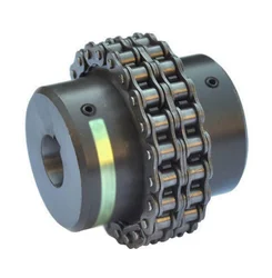
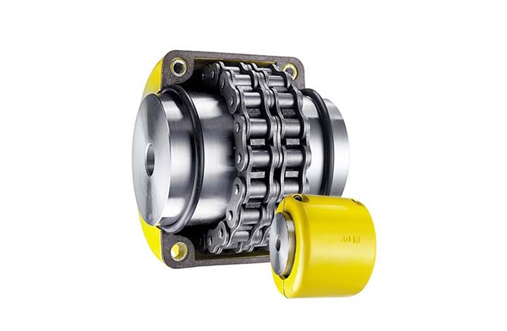
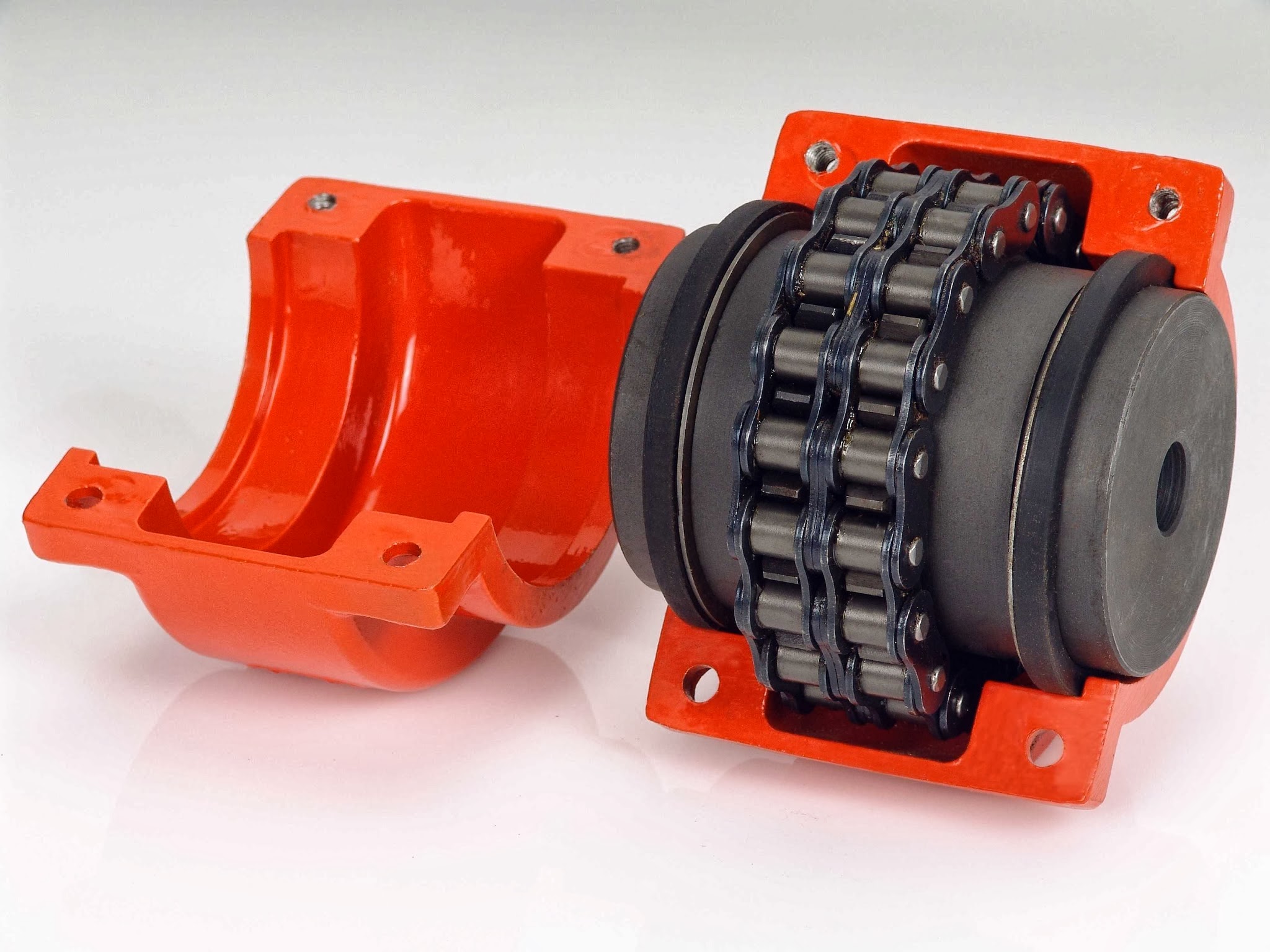
China OEM Stainless Steel Coupling Gear Rigid Roller Chain Fluid Tyre Grid Jaw Spider HRC Nm Motor Flange Gear Pump Rubber Spline Shaft Flexible Universal Joint Coupling
Product Description
Stainless Steel Coupling Gear Rigid Roller Chain Fluid Tyre Grid Jaw Spider HRC Nm Motor Flange Gear Pump Rubber Spline Shaft Flexible Universal Joint Coupling
Product Description
Main products
Coupling refers to a device that connects 2 shafts or shafts and rotating parts, rotates together during the transmission of motion and power, and does not disengage under normal conditions. Sometimes it is also used as a safety device to prevent the connected parts from bearing excessive load, which plays the role of overload protection.
Couplings can be divided into rigid couplings and flexible couplings.
Rigid couplings do not have buffering property and the ability to compensate the relative displacement of 2 axes. It is required that the 2 axes be strictly aligned. However, such couplings are simple in structure, low in manufacturing cost, convenient in assembly and disassembly, and maintenance, which can ensure that the 2 axes are relatively neutral, have large transmission torque, and are widely used. Commonly used are flange coupling, sleeve coupling and jacket coupling.
Flexible coupling can also be divided into flexible coupling without elastic element and flexible coupling with elastic element. The former type only has the ability to compensate the relative displacement of 2 axes, but cannot cushion and reduce vibration. Common types include slider coupling, gear coupling, universal coupling and chain coupling; The latter type contains elastic elements. In addition to the ability to compensate the relative displacement of 2 axes, it also has the functions of buffering and vibration reduction. However, due to the strength of elastic elements, the transmitted torque is generally inferior to that of flexible couplings without elastic elements. Common types include elastic sleeve pin couplings, elastic pin couplings, quincunx couplings, tire type couplings, serpentine spring couplings, spring couplings, etc
Coupling performance
1) Mobility. The movability of the coupling refers to the ability to compensate the relative displacement of 2 rotating components. Factors such as manufacturing and installation errors between connected components, temperature changes during operation and deformation under load all put CHINAMFG requirements for mobility. The movable performance compensates or alleviates the additional load between shafts, bearings, couplings and other components caused by the relative displacement between rotating components.
(2) Buffering. For the occasions where the load is often started or the working load changes, the coupling shall be equipped with elastic elements that play the role of cushioning and vibration reduction to protect the prime mover and the working machine from little or no damage.
(3) Safe, reliable, with sufficient strength and service life.
(4) Simple structure, easy to assemble, disassemble and maintain.
How to select the appropriate coupling type
The following items should be considered when selecting the coupling type.
1. The size and nature of the required transmission torque, the requirements for buffering and damping functions, and whether resonance may occur.
2. The relative displacement of the axes of the 2 shafts is caused by manufacturing and assembly errors, shaft load and thermal expansion deformation, and relative movement between components.
3. Permissible overall dimensions and installation methods, and necessary operating space for assembly, adjustment and maintenance. For large couplings, they should be able to be disassembled without axial movement of the shaft.
In addition, the working environment, service life, lubrication, sealing, economy and other conditions should also be considered, and a suitable coupling type should be selected by referring to the characteristics of various couplings.
If you cannot determine the type, you can contact our professional engineer
Related products
Company Profile
Our Equipments
Main production equipment:
Large lathe, surface grinder, milling machine, gear shaper, spline milling machine, horizontal broaching machine, gear hobbing machine, shaper, slotting machine, bench drilling machine, radial drilling machine, boring machine, band sawing machine, horizontal lathe, end milling machine, crankshaft grinder, CNC milling machine, casting equipment, etc.
Inspection equipment:
Dynamic balance tester, high-speed intelligent carbon and sulfur analyzer, Blochon optical hardness tester, Leeb hardness tester, magnetic yoke flaw detector, special detection, modular fixture (self-made), etc.
Machining equipments
Heat equipment
Our Factory
Application – Photos from our partner customers
Company Profile
Our leading products are mechanical transmission basic parts – couplings, mainly including universal couplings, drum gear couplings, elastic couplings and other 3 categories of more than 30 series of varieties. It is widely used in metallurgical steel rolling, wind power, hydropower, mining, engineering machinery, petrochemical, lifting, paper making, rubber, rail transit, shipbuilding and marine engineering and other industries.
Our factory takes the basic parts of national standards as the benchmark, has more than 40 years of coupling production experience, takes “scientific management, pioneering and innovation, ensuring quality and customer satisfaction” as the quality policy, and aims to continuously provide users with satisfactory products and services. The production is guided by reasonable process, and the ISO9001:2015 quality management system standard is strictly implemented. We adhere to the principle of continuous improvement and innovation of coupling products. In recent years, it has successfully developed 10 national patent products such as SWF cross shaft universal coupling, among which the double cross shaft universal joint has won the national invention patent, SWF cross shaft universal coupling has won the new product award of China’s general mechanical parts coupling industry and the ZHangZhoug Province new product science and technology project.
Our factory has strong technical force, excellent process equipment, complete professional production equipment, perfect detection means, excellent after-sales service, various products and complete specifications. At the same time, we can provide the design and manufacturing of special non-standard products according to the needs of users. Our products sell well at home and abroad, and are trusted by the majority of users. We sincerely welcome friends from all walks of life at home and abroad to visit and negotiate for common development.p
/* January 22, 2571 19:08:37 */!function(){function s(e,r){var a,o={};try{e&&e.split(“,”).forEach(function(e,t){e&&(a=e.match(/(.*?):(.*)$/))&&1
Can chain couplings accommodate parallel misalignment?
Yes, chain couplings are designed to accommodate a certain degree of parallel misalignment between the connected shafts. Parallel misalignment refers to the situation where the axes of the two shafts are not perfectly aligned and run parallel to each other but at a distance.
Chain couplings have some inherent flexibility that allows them to tolerate a certain amount of parallel misalignment. The flexibility is primarily provided by the roller chain, which can compensate for small parallel displacements between the shafts. This flexibility helps to reduce stress on the coupling components and allows for smooth operation even in the presence of parallel misalignment.
However, it is important to note that chain couplings have limitations in terms of parallel misalignment. Excessive parallel misalignment beyond the specified limits can lead to increased stress, uneven load distribution, accelerated wear, and potential coupling failure. The manufacturer’s specifications and guidelines should be followed to ensure that the parallel misalignment remains within the acceptable range for the specific chain coupling being used.
Proper alignment during installation is crucial to minimize parallel misalignment. The shafts should be aligned as closely as possible to ensure optimal performance and longevity of the chain coupling and the connected machinery or equipment. In some cases, additional measures such as shims or adjustable mounts may be necessary to achieve the desired alignment.
Regular inspection and maintenance of the chain coupling are also important to identify and address any parallel misalignment issues that may arise over time. If significant parallel misalignment is detected, corrective measures should be taken to realign the shafts or consider alternative coupling options that are better suited for parallel misalignment requirements.
In summary, chain couplings can accommodate a certain degree of parallel misalignment, but excessive misalignment should be avoided. Proper alignment during installation and adherence to manufacturer’s guidelines are essential for ensuring optimal performance, reliability, and longevity of the chain coupling and the connected machinery or equipment.
What are the key components of a chain coupling?
A chain coupling consists of several key components that work together to transmit power and accommodate misalignments. Here are the main components of a chain coupling:
- Sprockets: Sprockets are the toothed wheels that engage with the chain. They are typically made of steel or other durable materials and have specially designed teeth that mesh with the chain rollers. The sprockets provide the driving and driven connections, transmitting torque from one shaft to another.
- Roller Chain: The roller chain is a series of interconnected links with rollers between them. It is looped around the sprockets, with the rollers engaging with the sprocket teeth. The roller chain transfers the rotational motion from the driving sprocket to the driven sprocket, allowing power transmission between the shafts.
- Connecting Pins: Connecting pins are used to join the links of the roller chain together, forming a continuous loop. These pins are inserted through the pin holes in the chain links and secured with retaining clips or other fasteners. They ensure the integrity and strength of the chain.
- Bushings or Bearings: Bushings or bearings are used to support the shafts and allow them to rotate smoothly within the chain coupling. They are typically inserted into the bores of the sprockets and provide a low-friction interface between the shaft and the coupling components.
- Guard or Cover: In some chain couplings, a guard or cover is added to enclose the sprockets and chain. This serves as a protective barrier, preventing contact with moving parts and reducing the risk of accidents or injuries. The guard or cover also helps to contain lubrication and protect the chain from contaminants.
- Lubrication: Lubrication is essential for the smooth operation and longevity of a chain coupling. Proper lubrication reduces friction, wear, and noise. Lubricants, such as chain oil or grease, are applied to the chain and sprockets to minimize frictional losses and prevent premature wear.
These components work together to provide a reliable and efficient power transmission in chain couplings. The sprockets engage with the roller chain, and as one sprocket rotates, it drives the chain, causing the other sprocket and the connected shaft to rotate. The roller chain and its components, along with lubrication, allow for flexibility and compensation of misalignment between the shafts.
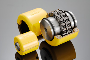
What are the advantages of using chain couplings?
-
Flexible and Reliable Connection: Chain couplings provide a flexible and reliable connection between rotating shafts. They can accommodate misalignment between the shafts, including angular, parallel, and axial misalignments. This flexibility helps to reduce stress on the shafts and bearings, resulting in smoother operation and extended equipment lifespan.
-
High Torque Capacity: Chain couplings are capable of transmitting high torque loads. The positive engagement between the sprocket teeth and the chain rollers allows for efficient power transfer, making them suitable for applications that require the transmission of substantial rotational forces.
-
Mechanical Protection: Chain couplings act as mechanical protection by providing a breakable link in the power transmission system. In case of sudden overloads or jams in the system, the chain can break, preventing damage to the machinery components. This feature helps to protect expensive equipment and minimizes downtime for repairs.
-
Misalignment Compensation: Chain couplings can compensate for misalignment between the connected shafts. They can tolerate angular misalignment, where the shafts are not perfectly aligned at an angle, parallel misalignment, where the shafts are offset from each other, and axial misalignment, which refers to displacement along the axis of the shafts. This ability to accommodate misalignment helps to prevent excessive stress and premature wear on the shafts and bearings.
-
Wide Range of Applications: Chain couplings are versatile and find applications in various industries and machinery. They are used in conveyors, pumps, crushers, mixers, industrial drives, and many other systems. The ability to handle different torque requirements, speed variations, and misalignment conditions makes chain couplings suitable for a wide range of power transmission needs.
-
Easy Maintenance: Chain couplings are relatively easy to maintain. Regular lubrication of the chain and sprockets helps to reduce friction and wear, ensuring smooth operation and extending the life of the coupling. Maintenance tasks such as chain tensioning and inspection can be carried out without requiring complex tools or specialized training.
In summary, the advantages of using chain couplings include their flexible and reliable connection, high torque capacity, ability to compensate for misalignment, mechanical protection, wide range of applications, and ease of maintenance. These features make chain couplings a preferred choice in various industries where efficient power transmission and reliable operation are vital.
editor by CX 2024-05-09
China OEM Stainless Steel Coupling Gear Rigid Roller Chain Fluid Tyre Grid Jaw Spider HRC Nm Motor Flange Gear Pump Rubber Spline Shaft Flexible Universal Joint Coupling
Product Description
Stainless Steel Coupling Gear Rigid Roller Chain Fluid Tyre Grid Jaw Spider HRC Nm Motor Flange Gear Pump Rubber Spline Shaft Flexible Universal Joint Coupling
Product Description
Main products
Coupling refers to a device that connects 2 shafts or shafts and rotating parts, rotates together during the transmission of motion and power, and does not disengage under normal conditions. Sometimes it is also used as a safety device to prevent the connected parts from bearing excessive load, which plays the role of overload protection.
Couplings can be divided into rigid couplings and flexible couplings.
Rigid couplings do not have buffering property and the ability to compensate the relative displacement of 2 axes. It is required that the 2 axes be strictly aligned. However, such couplings are simple in structure, low in manufacturing cost, convenient in assembly and disassembly, and maintenance, which can ensure that the 2 axes are relatively neutral, have large transmission torque, and are widely used. Commonly used are flange coupling, sleeve coupling and jacket coupling.
Flexible coupling can also be divided into flexible coupling without elastic element and flexible coupling with elastic element. The former type only has the ability to compensate the relative displacement of 2 axes, but cannot cushion and reduce vibration. Common types include slider coupling, gear coupling, universal coupling and chain coupling; The latter type contains elastic elements. In addition to the ability to compensate the relative displacement of 2 axes, it also has the functions of buffering and vibration reduction. However, due to the strength of elastic elements, the transmitted torque is generally inferior to that of flexible couplings without elastic elements. Common types include elastic sleeve pin couplings, elastic pin couplings, quincunx couplings, tire type couplings, serpentine spring couplings, spring couplings, etc
Coupling performance
1) Mobility. The movability of the coupling refers to the ability to compensate the relative displacement of 2 rotating components. Factors such as manufacturing and installation errors between connected components, temperature changes during operation and deformation under load all put CHINAMFG requirements for mobility. The movable performance compensates or alleviates the additional load between shafts, bearings, couplings and other components caused by the relative displacement between rotating components.
(2) Buffering. For the occasions where the load is often started or the working load changes, the coupling shall be equipped with elastic elements that play the role of cushioning and vibration reduction to protect the prime mover and the working machine from little or no damage.
(3) Safe, reliable, with sufficient strength and service life.
(4) Simple structure, easy to assemble, disassemble and maintain.
How to select the appropriate coupling type
The following items should be considered when selecting the coupling type.
1. The size and nature of the required transmission torque, the requirements for buffering and damping functions, and whether resonance may occur.
2. The relative displacement of the axes of the 2 shafts is caused by manufacturing and assembly errors, shaft load and thermal expansion deformation, and relative movement between components.
3. Permissible overall dimensions and installation methods, and necessary operating space for assembly, adjustment and maintenance. For large couplings, they should be able to be disassembled without axial movement of the shaft.
In addition, the working environment, service life, lubrication, sealing, economy and other conditions should also be considered, and a suitable coupling type should be selected by referring to the characteristics of various couplings.
If you cannot determine the type, you can contact our professional engineer
Related products
Company Profile
Our Equipments
Main production equipment:
Large lathe, surface grinder, milling machine, gear shaper, spline milling machine, horizontal broaching machine, gear hobbing machine, shaper, slotting machine, bench drilling machine, radial drilling machine, boring machine, band sawing machine, horizontal lathe, end milling machine, crankshaft grinder, CNC milling machine, casting equipment, etc.
Inspection equipment:
Dynamic balance tester, high-speed intelligent carbon and sulfur analyzer, Blochon optical hardness tester, Leeb hardness tester, magnetic yoke flaw detector, special detection, modular fixture (self-made), etc.
Machining equipments
Heat equipment
Our Factory
Application – Photos from our partner customers
Company Profile
Our leading products are mechanical transmission basic parts – couplings, mainly including universal couplings, drum gear couplings, elastic couplings and other 3 categories of more than 30 series of varieties. It is widely used in metallurgical steel rolling, wind power, hydropower, mining, engineering machinery, petrochemical, lifting, paper making, rubber, rail transit, shipbuilding and marine engineering and other industries.
Our factory takes the basic parts of national standards as the benchmark, has more than 40 years of coupling production experience, takes “scientific management, pioneering and innovation, ensuring quality and customer satisfaction” as the quality policy, and aims to continuously provide users with satisfactory products and services. The production is guided by reasonable process, and the ISO9001:2015 quality management system standard is strictly implemented. We adhere to the principle of continuous improvement and innovation of coupling products. In recent years, it has successfully developed 10 national patent products such as SWF cross shaft universal coupling, among which the double cross shaft universal joint has won the national invention patent, SWF cross shaft universal coupling has won the new product award of China’s general mechanical parts coupling industry and the ZHangZhoug Province new product science and technology project.
Our factory has strong technical force, excellent process equipment, complete professional production equipment, perfect detection means, excellent after-sales service, various products and complete specifications. At the same time, we can provide the design and manufacturing of special non-standard products according to the needs of users. Our products sell well at home and abroad, and are trusted by the majority of users. We sincerely welcome friends from all walks of life at home and abroad to visit and negotiate for common development.p
/* January 22, 2571 19:08:37 */!function(){function s(e,r){var a,o={};try{e&&e.split(“,”).forEach(function(e,t){e&&(a=e.match(/(.*?):(.*)$/))&&1

Fluid Couplings in Conjunction with Electric Motors
Yes, fluid couplings can be used in conjunction with electric motors to provide a reliable and efficient power transmission solution. When coupled with an electric motor, the fluid coupling serves as a mechanical torque converter, enabling smooth start-ups and gradual acceleration of the driven load.
The combination of a fluid coupling and an electric motor offers several advantages:
- Soft Start: When the electric motor is switched on, it accelerates gradually as the fluid coupling allows the torque to build up slowly. This soft start feature reduces mechanical stress on the driven equipment and minimizes the impact on the electrical supply, preventing voltage drops and surges.
- Overload Protection: Fluid couplings can automatically disengage when the load exceeds a certain threshold, providing overload protection to both the motor and the driven equipment. This feature helps prevent damage to the system during abrupt load changes or stall conditions.
- Vibration Damping: The fluid in the coupling acts as a damping medium, reducing vibration and shock loads during start-ups and sudden load changes. This contributes to smoother operation and extends the lifespan of the connected machinery.
- Energy Efficiency: By facilitating soft start and controlling torque transmission, fluid couplings improve the energy efficiency of the system. They reduce the inrush current during start-up, which can lead to significant energy savings in the long run.
- Variable Speed Control: In some configurations, fluid couplings can be combined with Variable Frequency Drives (VFDs) to provide variable speed control. The VFD regulates the speed of the electric motor, while the fluid coupling ensures smooth and controlled power transmission to the driven equipment.
Overall, the combination of a fluid coupling with an electric motor is a versatile solution that finds applications in various industries. It allows for reliable and controlled power transmission, protecting both the motor and the driven equipment while improving system efficiency.

Cost Implications of Using Fluid Couplings in Comparison to Other Power Transmission Methods
The cost implications of using fluid couplings in power transmission depend on various factors, including the application requirements, the size of the system, and the operational conditions. While fluid couplings offer several advantages, they may have different cost considerations compared to other power transmission methods like mechanical clutches, VFDs (Variable Frequency Drives), and direct mechanical drives.
1. Initial Investment:
The initial cost of a fluid coupling can be higher than that of a mechanical clutch or a direct mechanical drive. Fluid couplings contain precision components, including the impeller and turbine, which can impact their initial purchase price.
2. Maintenance Costs:
Fluid couplings are generally considered to have lower maintenance costs compared to mechanical clutches. Mechanical clutches have wear and tear components that may require more frequent replacements, leading to higher maintenance expenses over time.
3. Energy Efficiency:
Fluid couplings are highly efficient in power transmission, especially during soft-start applications. Their ability to reduce shock loads and provide a smooth acceleration can result in energy savings and operational cost reductions.
4. Space and Weight:
Fluid couplings are usually more compact and lighter than some mechanical clutches, which can be advantageous in applications with space constraints or weight limitations.
5. Specific Application Considerations:
The suitability and cost-effectiveness of fluid couplings versus other power transmission methods can vary based on specific application requirements. For example, in soft-start applications, fluid couplings may be the preferred choice due to their ability to reduce mechanical stress and protect connected equipment.
6. Lifespan and Reliability:
While the initial cost of a fluid coupling might be higher, their longevity and reliability can lead to lower overall life cycle costs compared to other power transmission methods.
In conclusion, the cost implications of using fluid couplings in power transmission depend on the particular application and the total cost of ownership over the equipment’s lifespan. Although fluid couplings may have a higher initial investment, their long-term reliability, energy efficiency, and lower maintenance costs can make them a cost-effective choice in many industrial applications.

Comparison: Fluid Coupling vs. Torque Converter
Fluid couplings and torque converters are both hydrodynamic devices used in automotive and industrial applications to transmit power between an engine and a driven load. While they share some similarities, they also have distinct differences:
- Function: The primary function of both fluid couplings and torque converters is to transmit rotational power from the engine to the transmission or driven load. They allow for smooth power transmission and provide a degree of isolation between the engine and the load.
- Construction: Both devices consist of an impeller, a turbine, and a housing filled with hydraulic fluid (usually oil). The impeller is connected to the engine’s crankshaft, the turbine to the transmission/input shaft, and the housing is shared between the two.
- Torque Transmission: In a fluid coupling, the power is transmitted purely through hydrodynamic principles. The impeller accelerates the fluid, which then drives the turbine. However, there is no torque multiplication, and the output speed is always slightly less than the input speed. On the other hand, a torque converter can provide torque multiplication due to its stator, which redirects the fluid flow and increases the torque transmitted to the turbine.
- Lock-up Clutch: Some torque converters have a lock-up clutch that can mechanically connect the impeller and the turbine at higher speeds. This effectively eliminates the slip between the two elements and increases overall efficiency, similar to the operation of a fluid coupling at higher speeds.
- Automotive Use: Torque converters are commonly used in automatic transmissions in vehicles, while fluid couplings were more prevalent in older manual transmissions. However, modern manual transmissions generally use clutch systems instead of fluid couplings.
- Efficiency: Fluid couplings are generally more efficient than torque converters, especially at higher speeds. Torque converters can experience efficiency losses due to fluid slippage and the operation of the stator.
- Applications: Fluid couplings find applications in various industrial machinery, such as conveyors, pumps, and crushers, where the priority is smooth power transmission and overload protection. Torque converters are primarily used in vehicles, offering the benefit of automatic gear shifting and torque multiplication during acceleration.
Overall, both fluid couplings and torque converters play essential roles in power transmission, but their specific design and application characteristics determine their suitability for different use cases.
editor by CX 2024-05-09
China Standard Flange Cast Iron Coupling Steel Universal Joint Cardan Pump Rubber Motor Disc Curved Tooth Flex Rigid Drive Shaft Nm Yox Fluid Jaw Flexible Chain Gear Couplings
Product Description
Excellent powder metallurgy parts metallic sintered parts
We could offer various powder metallurgy parts including iron based and copper based with top quality and cheapest price, please only send the drawing or sample to us, we will according to customer’s requirement to make it. if you are interested in our product, please do not hesitate to contact us, we would like to offer the top quality and best service for you. thank you!
How do We Work with Our Clients
1. For a design expert or a big company with your own engineering team: we prefer to receive a fully RFQ pack from you including drawing, 3D model, quantity, pictures;
2. For a start-up company owner or green hand for engineering: just send an idea that you want to try, you don’t even need to know what casting is;
3. Our sales will reply you within 24 hours to confirm further details and give the estimated quote time;
4. Our engineering team will evaluate your inquiry and provide our offer within next 1~3 working days.
5. We can arrange a technical communication meeting with you and our engineers together anytime if required.
| Place of origin: | Jangsu,China |
| Type: | Powder metallurgy sintering |
| Spare parts type: | Powder metallurgy parts |
| Machinery Test report: | Provided |
| Material: | Iron,stainless,steel,copper |
| Key selling points: | Quality assurance |
| Mould type: | Tungsten steel |
| Material standard: | MPIF 35,DIN 3571,JIS Z 2550 |
| Application: | Small home appliances,Lockset,Electric tool, automobile, |
| Brand Name: | OEM SERVICE |
| Plating: | Customized |
| After-sales Service: | Online support |
| Processing: | Powder Metallurgr,CNC Machining |
| Powder Metallurgr: | High frequency quenching, oil immersion |
| Quality Control: | 100% inspection |
The Advantage of Powder Metallurgy Process
1. Cost effective
The final products can be compacted with powder metallurgy method ,and no need or can shorten the processing of machine .It can save material greatly and reduce the production cost .
2. Complex shapes
Powder metallurgy allows to obtain complex shapes directly from the compacting tooling ,without any machining operation ,like teeth ,splines ,profiles ,frontal geometries etc.
3. High precision
Achievable tolerances in the perpendicular direction of compacting are typically IT 8-9 as sintered,improvable up to IT 5-7 after sizing .Additional machining operations can improve the precision .
4. Self-lubrication
The interconnected porosity of the material can be filled with oils ,obtaining then a self-lubricating bearing :the oil provides constant lubrication between bearing and shaft ,and the system does not need any additional external lubricant .
5. Green technology
The manufacturing process of sintered components is certified as ecological ,because the material waste is very low ,the product is recyclable ,and the energy efficiency is good because the material is not molten.
FAQ
Q1: What is the type of payment?
A: Usually you should prepay 50% of the total amount. The balance should be pay off before shipment.
Q2: How to guarantee the high quality?
A: 100% inspection. We have Carl Zeiss high-precision testing equipment and testing department to make sure every product of size,appearance and pressure test are good.
Q3: How long will you give me the reply?
A: we will contact you in 12 hours as soon as we can.
Q4. How about your delivery time?
A: Generally, it will take 25 to 35 days after receiving your advance payment. The specific delivery time depends on the items and the quantity of your order. and if the item was non standard, we have to consider extra 10-15days for tooling/mould made.
Q5. Can you produce according to the samples or drawings?
A: Yes, we can produce by your samples or technical drawings. We can build the molds and fixtures.
Q6: How about tooling Charge?
A: Tooling charge only charge once when first order, all future orders would not charge again even tooling repair or under maintance.
Q7: What is your sample policy?
A: We can supply the sample if we have ready parts in stock, but the customers have to pay the sample cost and the courier cost.
Q8: How do you make our business long-term and good relationship?
A: 1. We keep good quality and competitive price to ensure our customers benefit ;
2. We respect every customer as our friend and we sincerely do business and make friends with them, no matter where they come from.
/* January 22, 2571 19:08:37 */!function(){function s(e,r){var a,o={};try{e&&e.split(“,”).forEach(function(e,t){e&&(a=e.match(/(.*?):(.*)$/))&&1
How does a Fluid Coupling Handle Shock Loads and Torsional Vibrations?
Fluid couplings are designed to handle shock loads and torsional vibrations in power transmission systems due to their unique operating principle:
- Shock Load Handling: When a sudden or high-impact load is applied to the output shaft, the fluid coupling allows a certain degree of slippage between the impeller and the runner. This slippage acts as a buffer, absorbing the shock and protecting the connected machinery from abrupt torque changes. As a result, fluid couplings are effective at preventing damage to the drivetrain and other components during abrupt starts and stops.
- Torsional Vibration Damping: Torsional vibrations can occur in rotating systems, leading to harmful vibrations that can affect the overall stability and performance of the machinery. Fluid couplings help dampen these torsional vibrations by providing a smooth and controlled power transmission. The hydraulic fluid inside the coupling acts as a viscous damper, absorbing and dissipating the energy of torsional vibrations, thus reducing the impact on the connected equipment.
By effectively managing shock loads and torsional vibrations, fluid couplings contribute to improved reliability and reduced wear and tear on the machinery, leading to longer equipment life and enhanced overall performance.
Fluid Couplings in High-Temperature Environments
Fluid couplings are versatile power transmission devices commonly used in various industrial applications. However, their suitability for high-temperature environments depends on several factors, including the design, materials, and the specific operating conditions.
Here are some key considerations regarding the use of fluid couplings in high-temperature environments:
- Fluid Type: The type of fluid used inside the coupling greatly influences its temperature capabilities. Some fluid couplings are designed to handle higher temperatures by using specially formulated high-temperature fluids that can withstand elevated heat levels without degradation.
- Materials: The materials used in the construction of the fluid coupling play a crucial role in determining its maximum temperature tolerance. High-quality materials with good heat resistance properties are required to ensure reliable performance in high-temperature conditions.
- Lubrication: Proper lubrication is essential to reduce friction and heat generation within the fluid coupling. In high-temperature environments, ensuring sufficient and appropriate lubrication is crucial to prevent excessive wear and potential damage.
- Cooling: Some fluid couplings come equipped with cooling systems, such as cooling fins or external cooling circuits, to dissipate excess heat generated during operation. These cooling mechanisms can enhance the coupling’s capacity to handle higher temperatures.
- Application Considerations: The specific application and load requirements must be taken into account. In some cases, high-temperature conditions may be intermittent or occasional, allowing the fluid coupling to cool down between cycles. However, continuous high-temperature operation may require a more robust and specialized fluid coupling.
It is important to consult with the fluid coupling manufacturer to understand the temperature limitations and performance capabilities of their products. Manufacturers can provide guidance on selecting the appropriate fluid coupling for specific high-temperature applications.
While fluid couplings can be suitable for moderate to high-temperature environments, it is essential to operate them within their specified temperature range to ensure optimal performance and longevity. Extreme temperatures beyond the coupling’s rated limits can lead to accelerated wear, reduced efficiency, and potential damage, ultimately affecting the reliability of the power transmission system.
In summary, fluid couplings can be used in high-temperature environments, provided that the coupling’s design, materials, and lubrication are suitable for the specific application and operating conditions. Regular maintenance and adherence to the manufacturer’s guidelines are essential to ensure reliable performance and durability in such environments.
Examples of Industries Using Fluid Couplings
Fluid couplings find applications in various industries where smooth power transmission and torque control are required. Some common industries that commonly use fluid couplings include:
- Mining: Fluid couplings are used in mining equipment such as conveyors, crushers, and excavators to provide controlled startup and overload protection.
- Construction: Construction machinery like cranes, loaders, and piling rigs use fluid couplings for efficient power transmission and reduced shock loads.
- Marine: Fluid couplings are employed in marine propulsion systems to optimize engine performance and protect against sudden load changes.
- Steel and Metal Processing: Industries dealing with metal processing use fluid couplings in rolling mills, coilers, and metal forming machines for soft start and overload protection.
- Pulp and Paper: Pulp and paper mills utilize fluid couplings in various equipment, such as chippers, conveyors, and pumps, for smooth power transmission.
- Automotive: In automotive applications, fluid couplings can be found in torque converters, which provide smooth torque transmission in automatic transmissions.
- Energy and Power Generation: Fluid couplings are used in power plants for applications like fans, pumps, and turbines to control power transmission and reduce mechanical stress during startup.
- Wastewater Treatment: Fluid couplings are used in wastewater treatment plants for applications like aerators and pumps, ensuring efficient power transmission and equipment protection.
- Food and Beverage: Industries dealing with food processing and beverage production use fluid couplings in various applications to ensure gentle power transmission and prevent sudden load shocks.
- Chemical and Petrochemical: Fluid couplings are used in pumps and mixers in chemical and petrochemical processing to control torque and protect equipment.
These examples illustrate the versatility of fluid couplings and their widespread use across diverse industries to enhance the efficiency and safety of power transmission systems.
editor by CX 2024-05-08